Wiring diagram sequence of operation – Manitowoc Ice FLAKE/CHIPLET QF0400 User Manual
Page 78
Electrical System
Section 6
6-16
Part No. 80-1214-3
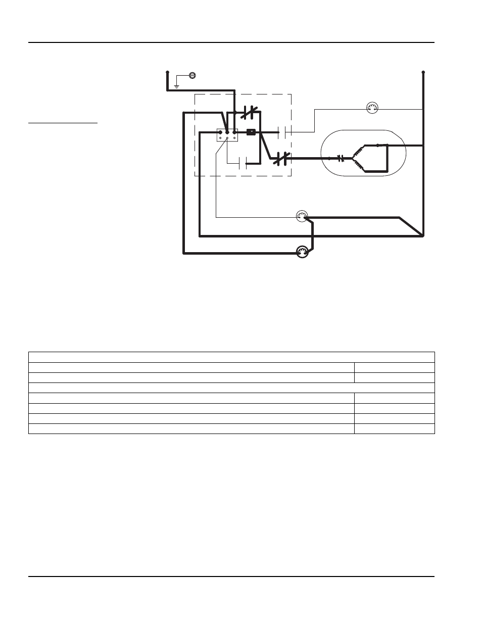
Wiring Diagram Sequence of
Operation
QF2200
Initial Start-Up or Start-Up After
Automatic Shut-Off
1A. WATER FLUSH
Immediately after placing the toggle
switch in “ICE”, the dump valve
solenoid, and gearbox are energized.
After 45 seconds the dump valve de-
energizes.
SV3043
RELAY
K1
RELAY
K2
RELAY
K3
RELAY K4
(25)
L1
L2
(54)
(53)
LIQUID LINE
SOLENOID
CENTRIFUGAL
SWITCH
(65)
INTERNAL
OVERLOAD
START
RUN
GEARMOTOR
WATER FLOAT
VALVE COIL
DUMP VALVE
COIL
(56)
(55)
(22)
(51)
(52)
7 AMP
FUSE
GROUND
1A. Water Flush (45 Seconds)
Toggle Switch
ICE
Bin Level Probe
Open (No Ice Contact)
Control Board Relays
#1
Liquid Line Solenoid Valve
OFF
#2
Dump Valve
ON
#3
Gear Motor
ON
#4
Water Float Valve Solenoid Coil
OFF
Revised 8/2003
This manual is related to the following products: