Notching, Using the notching station, Removing & installing notch dies – Grizzly 50/65 Ton Ironworker G0646 User Manual
Page 27
G0646/G0647 50/65 Ton Ironworker
-25-
Notching
The notching station sets up to make notches of
varying sizes and shapes in flat bar mild steel
stock. The limit stops are adjustable to set the
most efficient stroke length for your operation
(refer to
Page 33).
Stay within the following notching capacities for
your machine:
Model G0646
Maximum Thickness ...........................
5
⁄
16
" (8mm)
Maximum Notch Width .................... 1
3
⁄
8
" (35mm)
Maximum Notch Depth ....................... 3" (75mm)
Model G0647
Maximum Thickness ..........................
3
⁄
8
" (10mm)
Maximum Notch Width .................... 1
5
⁄
8
" (42mm)
Maximum Notch Depth ..................... 4" (100mm)
Using the Notching Station
1. Set the controls to Punch and Inch, then
raise the notching die so that you can insert
the workpiece.
2. Brush one of the lubricants from Figure 18 on
Page 22 or an equivalent onto both sides of
the workpiece.
3. Position the workpiece on the table and
under the tooling, then use the table guides
and other devices to support the workpiece
(see
Figure 24).
notching station tips
4. Set the controls to Notch and Normal, then
turn the motor
ON.
5. Stand clear of the machine and use the pedal
actuator to perform the notching operation.
Note: When the notching operation is com-
plete, the die will automatically raise up out
of the workpiece.
Removing & Installing Notch Dies
Tools Needed
Qty
Hex Wrenches 4, 5, 6, 8, 14mm ..............1 Each
Wrench 19mm ................................................... 1
Feeler Gauges 1mm, 3mm ......................1 Each
To remove the notch dies:
1. Set the controls to Punch and Inch, raise the
die to its uppermost position above the notch-
ing station, then turn the motor
OFF.
2. DISCONNECT MACHINE FROM POWER!
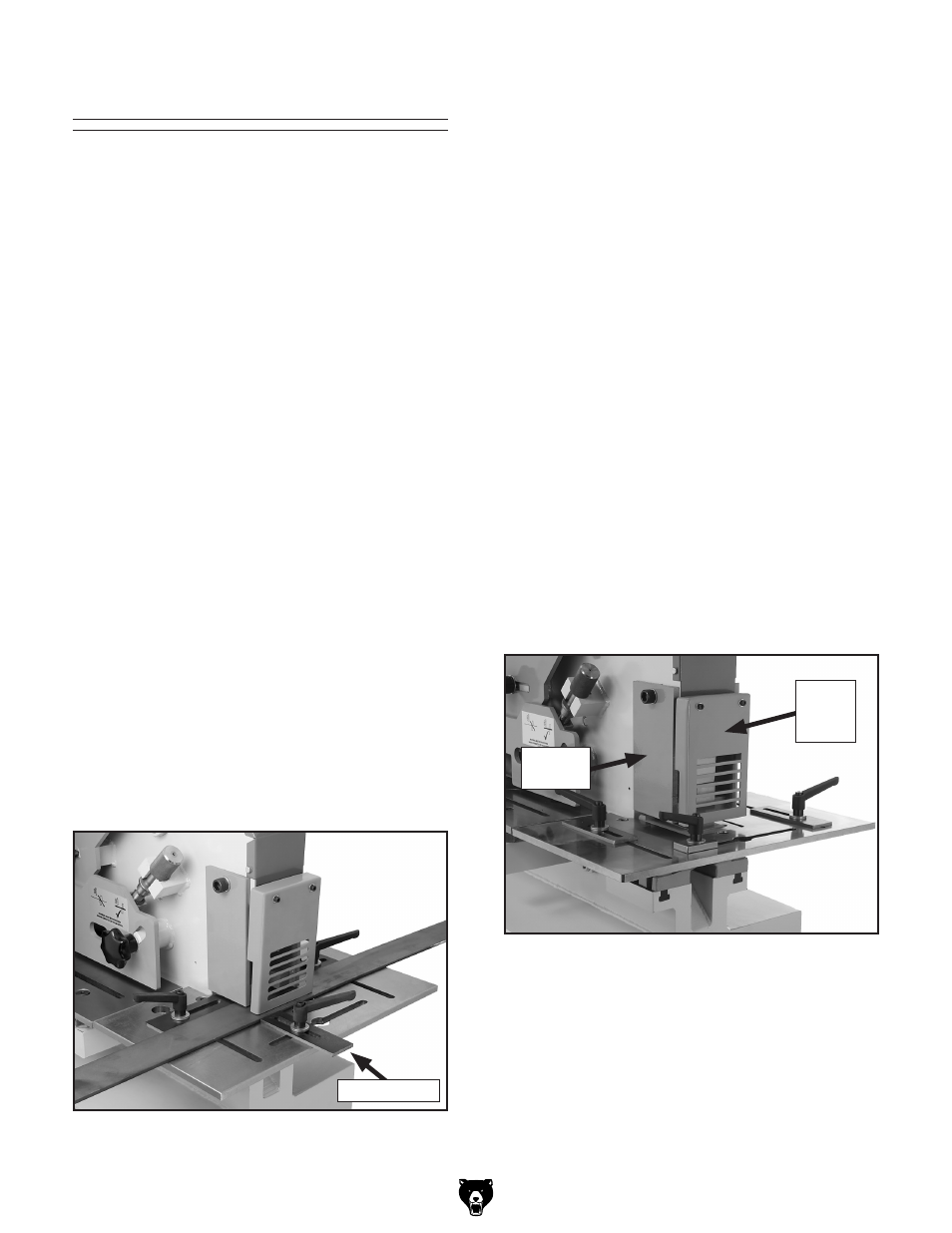
3. Remove the stripper plates from both sides
of the notching station and the front safety
guard (see
Figure 25).
Figure 25. Notching station stripper plate and
front safety guard.
Stripper
Plate
Front
Safety
Guard
Figure 24. Typical workpiece positioning for the
notching station.
Table Guide