Iii. the indicator signal chart & default, Led signal, Audio – Gianni Industries DK100 User Manual
Page 2: Default value, Iv. wiring diagram: attention, V. operation instruction
Copyright © Gianni Industries, Inc. All Rights Reserved.
P-MU-DK100 Ver.B Published on 2007.09.12 Page: 2/ 3
III. The indicator signal chart & Default:
Green LED
Relay activated
Red LED
Power on, stand-by
Yellow LED
Programming mode
1 Flashing Yellow LED
Key-in Code Confirmed
Blue LED
Controller Stand-by
LED signal
Flashing Blue LED
Controller Locked
Bi
Key-in, Effective PIN codes
Bi- x 2
Entering or Exiting from the Program mode
Bi- x 3
Data computing error, other operation
mistakes
Audio
Bi- x 5
Master Code reset to default(12345)or
remove all stored user codes
Master code
12345 (changeable)
Time delay of relays
5 seconds
Time delay of Keypad
5 seconds
Time delay of programming mode
60 seconds
Default value
Time delay of Invalid PIN Lock-out
12345 (changeable)
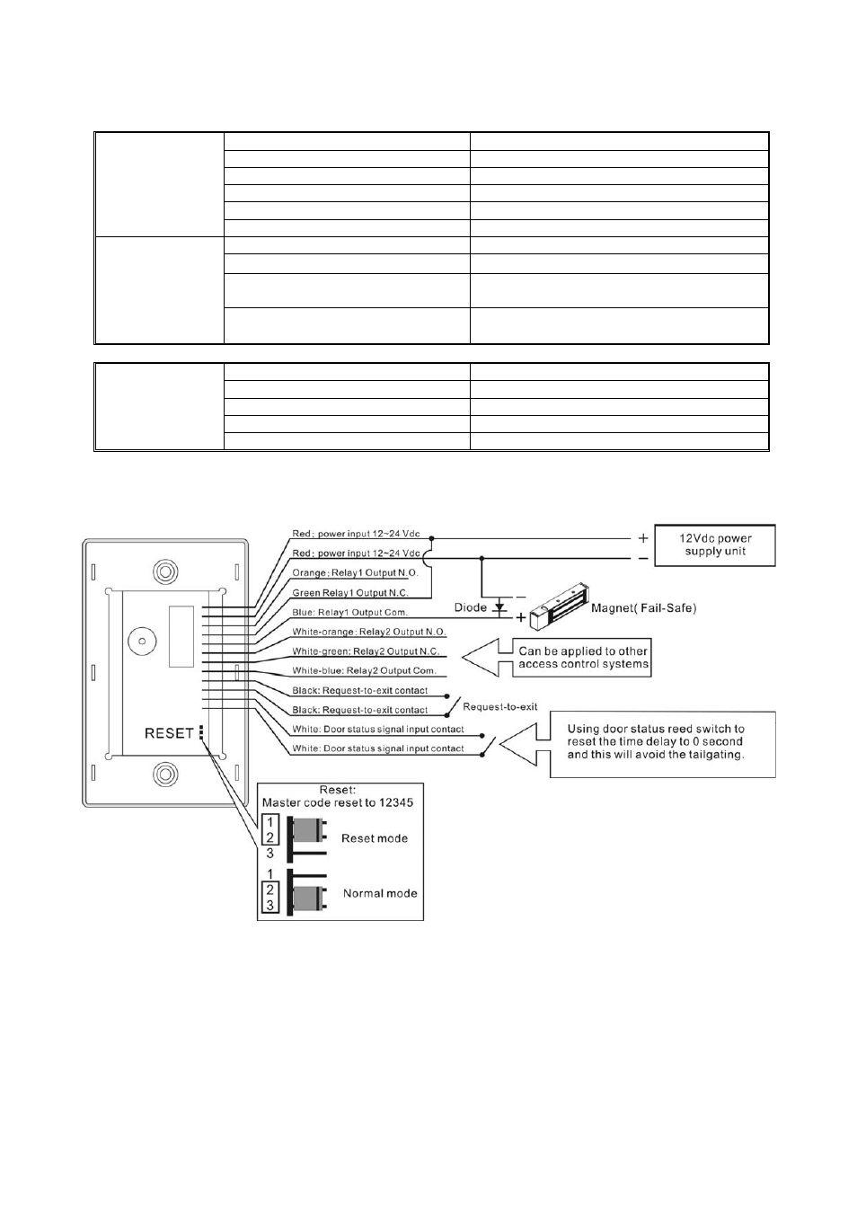
IV. Wiring Diagram:
Attention
:
The varistor or diode must be connected across the lock terminal (electric strike...) operated by the
device. The varistor controls the overload produced by the strike coil (EMP)
Cutting spare delay time after door closes for anti-passback: Time delay settled in 10 seconds. If the
door is closed in 3 seconds, the remaining 7 seconds will be ignored and door locks automatically once
the door closes.
V. Operation Instruction: