Step 5 set jumpers – Gateway ADAC ULTRA2 S466 User Manual
Page 73
Chapter 6 Hardware Installation
59
Step 5 Set Jumpers,
Continued
J1 Termination Enable J1 is a three-pin header that specifies hardware or
software control of SCSI termination.
Type of SCSI Termination
J1 Setting
Software control of SCSI termination via drive
detection.
Short Pins 1-2
Permanently disable all onboard SCSI termination.
Short Pins 2-3
Permanently enable all onboard SCSI termination.
OPEN
J3 I2C Interface Connector J3 is a four-pin header that allows the i960JX
core processor to serve as a master and slave device that
resided on the I2C bus when used with the I2C Bus
Interface Unit. Attach a four-wire cable from J3 to the I2C
Bus Interface Unit.
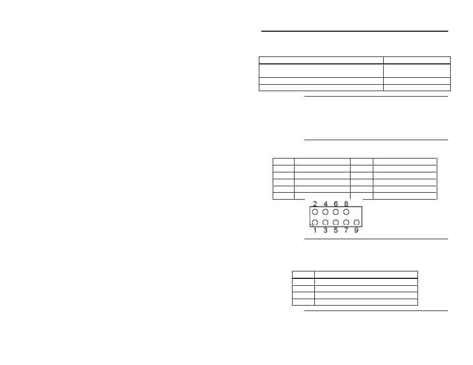
J4 Serial Port
J4 is a 9-pin berg that attaches to a serial cable. The pinout:
Pin
Signal Description
Pin
Signal Description
1
Carrier Detect
2
Data Set Ready
3
Receive Data
4
Request to Send
5
Transmit Data
6
Clear to Send
7
Data Terminal Ready
8
Ring Indicator
9
Ground
J5 Hard Disk LED J5 is a four-pin connector that attaches to a cable that
connects to the hard disk LED mounted on the computer
enclosure. The LED indicates data transfers.
Pin
Description
1
High
2
SCSI Activity Signal
3
SCSI Activity Signal
4
High
Cont’d