2 logical address – FUJITSU MHK2090AT User Manual
Page 197
Operations
6-8
C141-E088-03EN
6.2.2 Logical address
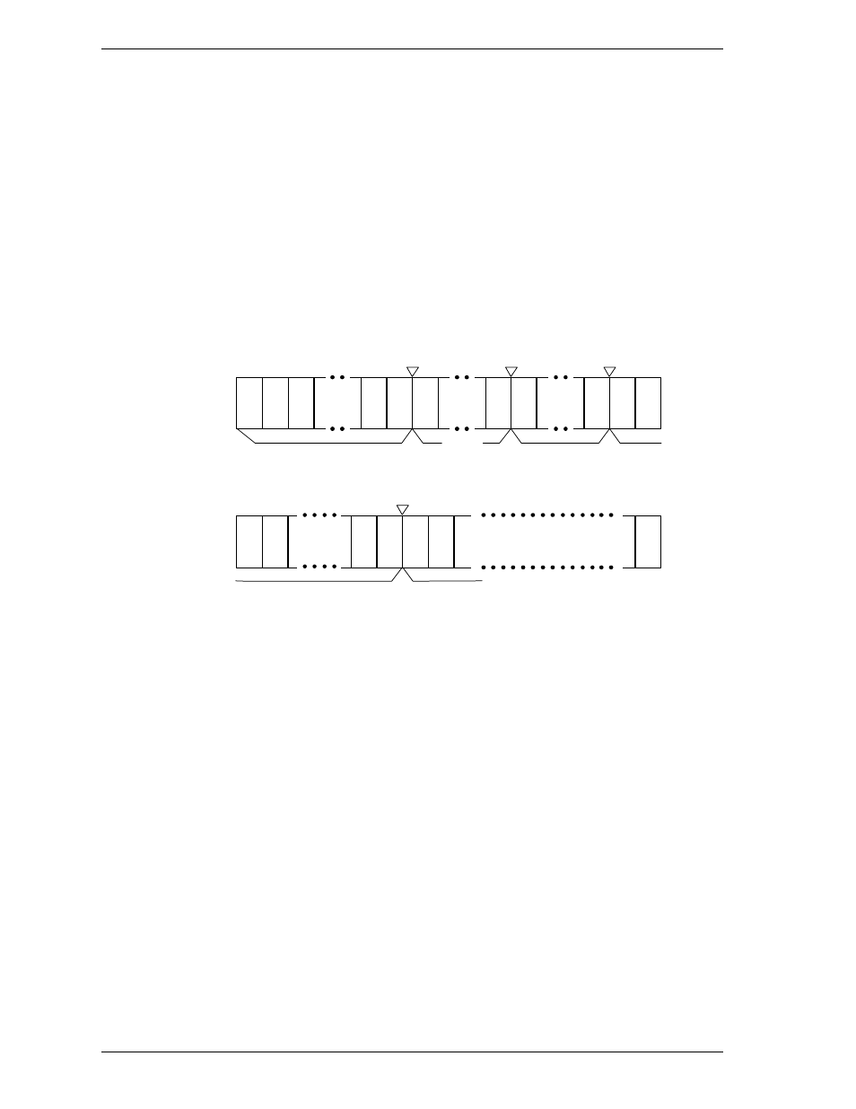
(1) CHS mode
Logical address assignment starts from physical cylinder (PC) 0, physical head
(PH) 0, and physical sector (PS) 1 and is assigned by calculating the number of
sectors per track that is specified by the INITIALIZE DEVICE PARAMETERS
command. If the last sector of a physical track is used, the track is switched and
the next logical sector is placed in the initial sector of the subsequent physical
track.
Figure 6.5 shows an example of 6 heads configuration. (assuming there is no track
skew).
LS2
LS1
LS1
LS1
LS
63
Physical head 0
Physical cylinder 0
127
126
64
63
62
LH8
LH1
LH0
3
2
1
Physical sector
LS
63
LS
63
505 506
504
LS4
LS3
LS
63
ex: Zone 0 in 6-head device
Physical parameter
– Physical head: 0 to 5
– Physical sector: 1 to 506
Specification of INITIALIZE DEVICE PARAMETERS command
– Logical head: 0 to 15
– Logical sector: 1 to 63
Physical head 0
Physical cylinder 1
61
62
LH9
LH8
2
1
Physical sector
LS2
LS1
Figure 6.5 Address translation (example in CHS mode)