Figure 33. access menus, Figure 34. vcr access display, Figure 35. multiplexer access display – Interlogix KTD-405 Series User Manual User Manual
Page 33
Chapter 3
Programming
29
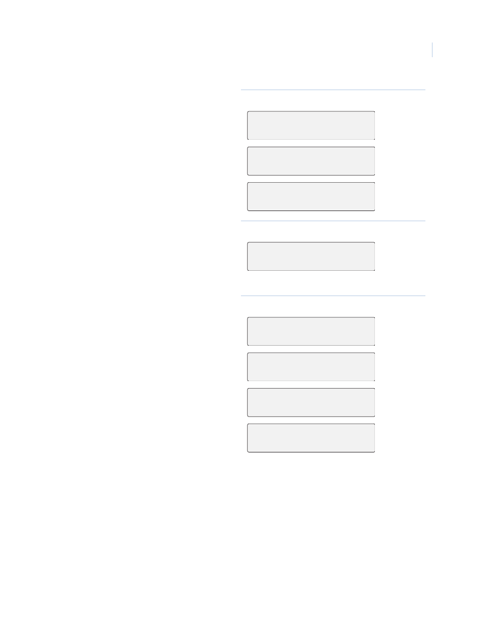
6. The following access menus (Figure 33) are
used to restrict the keypad from addressing
specified sites in the system.
The access menus enable you to allow access
for each camera, monitor, DSR/VCR, and
multiplexer. To move from one type of
access menu to another, press or .
Note: If you do not want to interrupt viewing at another
keypad, program the keypad to address only the
monitors within its view.
Figure 33. Access menus
7. Pressing + displays the following menu
(Figure 34). The VCR output can be
assigned an input number on the matrix
switcher. When a VCR is called, the matrix
switcher switches to the assigned input.
Enter a number from 1 through 511, or enter
0 for NONE.
Figure 34. VCR access display
8. These menus (Figure 35) are used to
configure multiplexers.
9. Use or or the joystick to scroll through
multiplexer manufacturers.
10. If the DVMRe/multiplexer’s outputs are
connected to an input on a matrix switcher,
enter the input number (1 to 511, or 0 for
none).
11. Enter the number of outputs (1 to 5)
connected to the matrix switcher. This
returns you to the MPLX xx ACCESS menu.
Note: Outputs must be connected in sequential order to
inputs if more than one output from a single DVMRe/
mux is used.
Figure 35. Multiplexer access display
CAMERA 000 ACCESS?
YES
MONITOR 01 ACCESS?
YES
DSR/VCR 01 ACCESS?
YES
VCR 01 MATRIX
INPUT:
MPLX 01 ACCESS?YES
(+)=YES (-)=NO
MPLX01 BRAND
DVMRE DUP
MPLX 01 MATRIX
INPUT?
SELECT MAX OUTPUTS:
02