Hardware and wiring – Industrial Data Systems IDS DT220 User Manual
Page 41
DT220 Users Manual version 1.a
Hardware & Wiring
37
Hardware and Wiring
This section describes installation and wiring information for the interface ports. There
are three bi-directional serial ports, one parallel printer port, 7 TTL inputs and 8 TTL
outputs. In addition, there is an optional load cell input port.
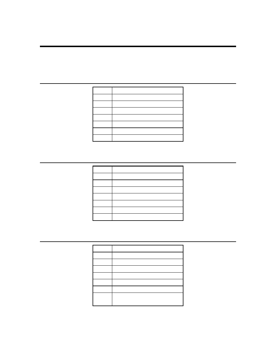
TB1 - TTL Output 1- 6, gnd
Pin # Signal Name
1
TTL output 1
2
TTL output 2
3
TTL output 3
4
TTL output 4
5
TTL output 5
6
TTL output 6
7
Ground (GND)
TB2 - TTL Output 8 & 9, gnd, +5V
Pin # Signal Name
1
TTL output 7
2
TTL output 8
3
Ground (GND)
4
Ground (GND)
5
Ground (GND)
6
+5V
7
+5V
TB3 - TTL Input 1 – 7 ( TTL Input 7 = Cal Function Lock)
Pin # Signal Name
1
TTL input 1
2
TTL input 2
3
TTL input 3
4
TTL input 4
5
TTL input 5
6
TTL input 6
7
TTL input 7 (Function Lock)
Jump to ground to unlock