Pulsafeeder Digital Glycol Feeder DGF2 User Manual
Page 31
26
c) While observing the Pressure Gauge, slowly turn the Pressure Relief Valve counter-
clockwise until you see liquid flow or the pressure drops. Keep track of the number of
turns, as they will be used at a later step.
The Pressure LED should illuminate RED.
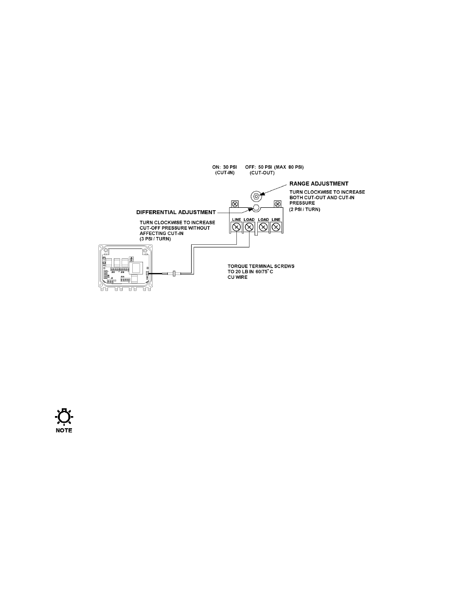
The Pressure gauge will show the pump start pressure. Adjust the Pressure Switch Range
Adjustment Screw if the indicated start pressure is not correct for your application. To
increase the trip pressure, turn the Pressure Switch Range Adjustment Screw clockwise.
To decrease the trip pressure, turn the Pressure Switch Range Adjustment Screw counter
clockwise.
Figure 22 – High Pressure switch
10. Turn the Pressure Relief Valve clockwise to restore it to it’s previous setting.
11. Slowly open the Main Shutoff Valve.
a) Observe the pressure at which the Pressure LED shuts off.
b) Adjust the Pressure Switch Range Adjustment screw (refer to Figure 22) if the indicated
pressure is not correct for your application.
c) Adjust the Pressure Relief valve setting clockwise until you see there is no liquid flow.
12. Repeat steps 7 – 11 until you have set the range.
13. Check that there is no flow. Adjust the Pressure Relief Valve if necessary.
You may need to repeat this step several times before the system is “fine tuned” to the
desired operating pressure.
There is an optional low pressure switch (Pulsafeeder Part #: 12-140-01) available for the Digital
Glycol Feeder system. If you have this switch, follow steps 1 – 13 to perform the start up
procedure. Figure 23 below shows the switch component layout.