2 electrical wiring – Pulsafeeder Digital Glycol Feeder DGF2 User Manual
Page 17
12
2.2 Electrical
Wiring
The procedure you will use to make the electrical connections is dependent on the option
package you select (refer to Figure 2 – Options List).
2.2.1 115VAC Pre-Wired Unit Connections
2.2.1.1
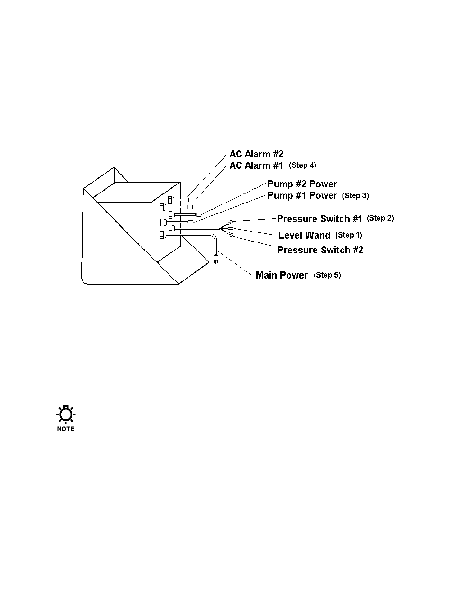
Dual AC Alarm Connection
Figure 10 – Dual AC Alarm Connection
1. Plug the 2-wire Molex connector tagged Level Wand into its mate on the end of the PVC
wand (low liquid level switch).
2. Plug the 2-wire Molex connector tagged Pressure Switch #1 into its mate on the pressure
switch attached to the closed loop system.
3. Plug the pump into the Pump #1 Power receptacle (pigtail).
4. Plug the Alarm Indicators (e.g.: warning light) into the associated AC Alarm (#1 & #2)
receptacles (power pigtail).
5. Plug in the Main Power cord.
For the purpose of this manual, the DGF1 is used as the example. If you have a DGF2
repeat steps 2 and 3 for the second pressure switch and pump.