Installation - hard ware 2-2, Equipment complement 2-1, Unpacking and inspection 2-1 – Anritsu ME7840A User Manual
Page 28: Chapter 2 installation, Introduction -1, Equipment complement -1, Unpacking and inspection -1, Installation - hardware installation
A listing of the non-optional-accessories always supplied with PATS is
listed below. The cables and terminators are shown in Figures 2-3 and
2-2, on page 2-3.
Item
Part No.
Quantity
Broadband Termination
28N50LF
2
Control Cable
803-49
1
RF Cables, Type N connectors (front)
15NN50-0.25B
3
RF Cables, SMA connectors (rear)
15NN50-0.35B
4
2-4
INSTALLATION -
HARDWARE
System hardware is set-up is a straight-forward process. Follow the
steps below in sequence to ensure a trouble free installation.
Step 1.
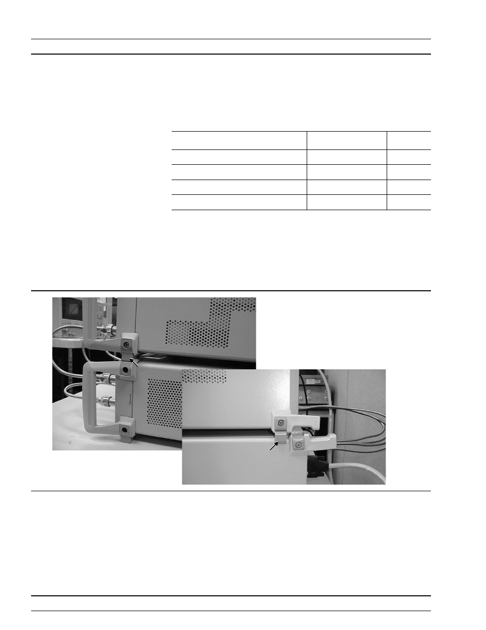
Place the MS462XC on top of the MS4782X Test Set. Figure
2-1 shows how the green colored feet on the case of each unit
stack on each other.
Step 2.
Install the three front RF interconnect cables. Figure 2-3 (fol-
lowing page) shows the installation of the RF interconnect ca-
bles between the front panel of the MS462XC and the front
panel of the Test Set. Table 2-1 lists the applicable connectors
by designation or function.
INSTALLATION - HARDWARE
INSTALLATION
2-2
ME 7840A OMM
Foot
Foot
Figure 2-1. ME7840A Component Assembly