Expansion port mounting – VEGA LUCOM EDGE router ER75i v2 SL USER’S GUIDE User Manual
Page 30
EXPANSION PORT MOUNTING
30
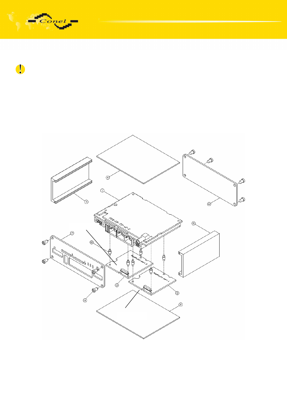
3.2. Expansion port mounting for ER75i v2 SL
Attention! Expansion port PORT1 and PORT2 include when the router ER75i v2 SL
is switched off.
After unscrewing four screws (position 11) on the rear panel (position 6)
and removing it is possible to take out the B-RB-v2 motherboard (position 1). The expansion
port PORT1 (position 2) is connected to connector J8 (see below) of the router B-RB-v2
motherboard (position 1) from TOP side. The expansion port PORT2 (position 3)
is connected to connector J3 (see below) of the router B-RB-v2 motherboard (position 1)
from TOP side. The expansion port is mounted to the motherboard by the help of three
spacers (position 10). After mounting the expansion port the box is screwed together
by the help of four screws(position 11).
Connector J8
Connector J3
LUCOM GmbH * Ansbacher Str. 2a * 90513 Zirndorf * Tel. 09127/59 460-10 * Fax. 09127/59 460-20 * www.lucom.de