Expansion port mounting – VEGA LUCOM EDGE router ER75i v2 SL USER’S GUIDE User Manual
Page 16
EXPANSION PORT MOUNTING
16
2.8.6.
Connection of the Port1 Connector – M-BUSD
Panel socket RJ45.
Pin
number
Signal
mark
Description
Data flow direction
1
GND
Signal and supply ground
2
GND
Signal and supply ground
3
TxRx-
M-BUS B (-)
Input/Output
4
TxRx+
M-BUS A (+)
Input/Output
5
TxRx-
M-BUS B (-)
Input/Output
6
TxRx+
M-BUS A (+)
Input/Output
7
+12 V EXT External power supply
8
+12 V EXT External power supply
ATTENTION! External supply is for converter M-BUSD!
If galvanic separation is required the converter must have external power supply.
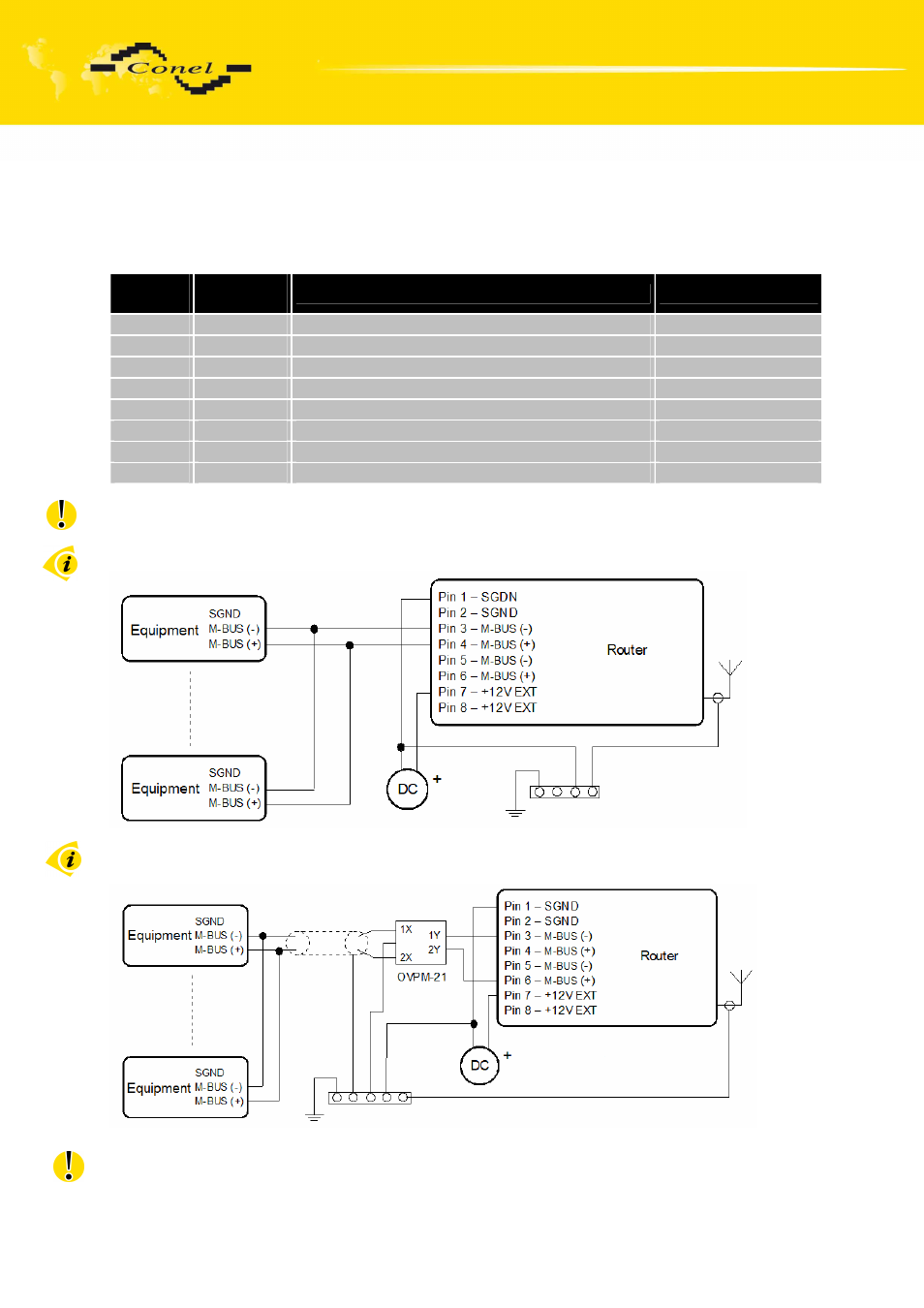
Circuit example of the equipment with a router with data cable length less than 10 m:
Circuit example of the equipment with a router with data cable length more than 10 m:
With a M-BUS data cable more than 10m it is necessary to use overvoltage protection
on the router side!
LUCOM GmbH * Ansbacher Str. 2a * 90513 Zirndorf * Tel. 09127/59 460-10 * Fax. 09127/59 460-20 * www.lucom.de