Figure 9-2, Drawing legend, Interrupt pin – Maxim Integrated DS33R11 User Manual
Page 49
DS33R11 Ethernet Mapper with Integrated T1/E1/J1 Transceiver
49 of 344
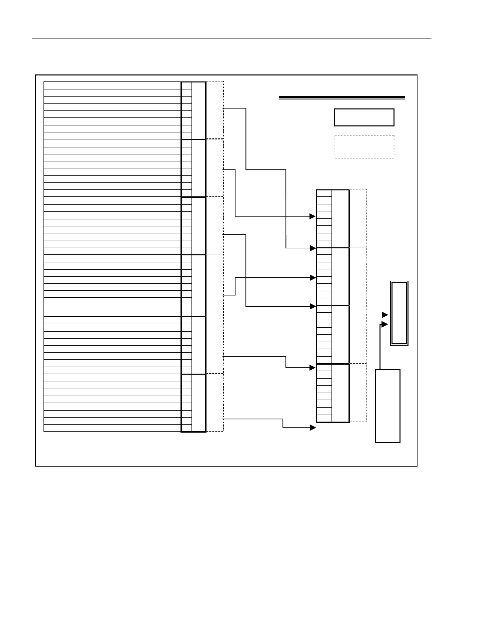
Figure 9-2. Device Interrupt Information Flow Diagram
Receive FCS Errored Packet
7
Receive Aborted Packet
6
Receive Invalid Packet Detected
5
Receive Small Packet Detected
4
Receive Large Packet Detected
3
Receive FCS Errored Packet Count
2
Receive Aborted Packet Count
1
Receive Size Violation Packet Count
0
LI.RPPSL
LI.RPPSRIE
7
6
5
4
3
2
1
Transmit Errored Packet Insertion Finished
0
LI.TPPSRL
LI.TPPSRIE
7
6
5
4
SAPI High is not equal to LI.TRX86SAPIH
3
SAPI Low is not equal to LI.TRX86SAPIL
2
Control is not equal to LI.TRX8C
1
Address is not equal to LI.TRX86A
0
LI.RX86S
LI.RX86LSIE
7
6
5
4
Transmit Queue FIFO Overflowed
3
Transmit Queue Overflow
2
Transmit Queue for Connection Exceeded Low Threshold
1
Transmit Queue for Connection Exceeded High
Threshold
0
LI.TQCTLS
LI.TQTIE
7
6
5
4
Receive Queue FIFO Overflowed
3
Receive Queue Overflow
2
Receive Queue for Connection Exceeded Low Threshold
1
Receive Queue for Connection Exceeded High Threshold
0
SU.Q
CRLS
SU.Q
RIE
7
6
5
4
Performance Monitor Update
3
Bit Error Detected
2
Bit Error Count
1
Out Of Synchronization
0
BSRL
BSRIE
Drawing Legend:
Interrupt Status
Registers
Register Name
Interrupt
Enable
Registers
Register Name
Interrupt Pin
7
6
5
4
3
2
1
0
GL.TRQIS
GL.TRQIE
7
6
5
4
3
2
1
0
GL.LIS
GL.LIE
7
6
5
4
3
2
1
0
GL.SIS
GL.SIE
7
6
5
4
3
2
1
0
GL.BIS
GL.BIE
Interrupts from
T1/E1/J1 Transceiver