Hitachi GR2000 User Manual
Page 207
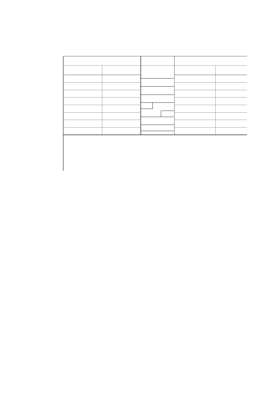
9-pin on Router Side
Connection
9-pin on Setup Console Side
Pin Number
Signal Name
Pin Number
Signal Name
5
SG
5
GND
3
SD
2
RX
2
RD
3
TX
7
RS
1
DCD
8
CS
8
CTS
1
CD
7
RTS
6
DR
6
DTR
4
ER
4
DSR
Note 3:
In order to connect the RM serial interface of this device with a modem, use a straight cable to conn
the AT interchangeable machine and the modem.
Note 4:
The model connected to this device is set to the automatic signal reception.