New1-8 switch and function of led indication -26 – Hitachi GR2000 User Manual
Page 128
GR2000 Installation Guide
3-26
GR2K-GA-1002
Rev. 6.03
Precautions when connecting NWVX-8
Relationship between connection of cables supplied with VX-8 and LINE number
NWVX-8 is supplied with the cables attached to VX-8.
Connect the cables attached to VX-8 (100-pin high-density connector) as shown
below.
The tips of the cables attached to VX-8 have connecting sections for the same
50-pin half-pitch connectors (LINE 0 to LINE 7) as in NWVX-4.
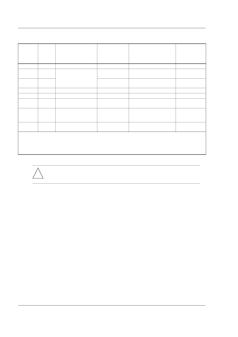
Table 3-27 NEW1-8 switch and function of LED indication
ACT
LINE ERR
(*1)
T/R
LOOP
(*1)
Line state
Detail of state
State as seen by SXMP
Line state
indication in
MMI and
browser
--
(*3)
Being initialized.
Being initialized (3).
initialize
G
(*3)
Being operated
In normal
operation.
In standby (3).
active up
Y
(*3)
Line fault being
occurred.
In operation (line fault being
occurred (8).
active down
G
(*3)
Line test.
Line being tested (9).
test
--
--
In fault.
In fault (4).
fault
--
--
Command being
blocked.
In maintenance (10).
closed
--
--
Not used.
Configuration
definition not set
yet
Not used.
Configuration definition not
set yet. (10)
unused
--
--
Configuration definitions
not agreed.
Configuration definitions not
agreed. (11)
mismatch
(*1): G: Lights in green, Y: Lights in yellow, -: Goes off
(*2): Meaning and value of SMNP private MIB and gr2kPhysLineOperStatus
(*3): The T/R LED lights and goes off by H/W. In lighting conditions, this LED lights in green when the logical value of
send and receive data is "0". The LED lights in green when lighting conditions are detected irrespective of the line
state.
*
Note: When making connection with the cable having come off, repeat cancellation of the LED
and lighting up of the ERR (or ACT) LED to retry the CLOSE/OPEN operation of the line.