7 rmb-io(h), 8 csw, 7 rmb-io(h) -15 – Hitachi GR2000 User Manual
Page 117: 8 csw -15, Bcu switch and function of led indications -15
Component Details
GR2K-GA-1002
3-15
Rev. 6.03
3.3.7
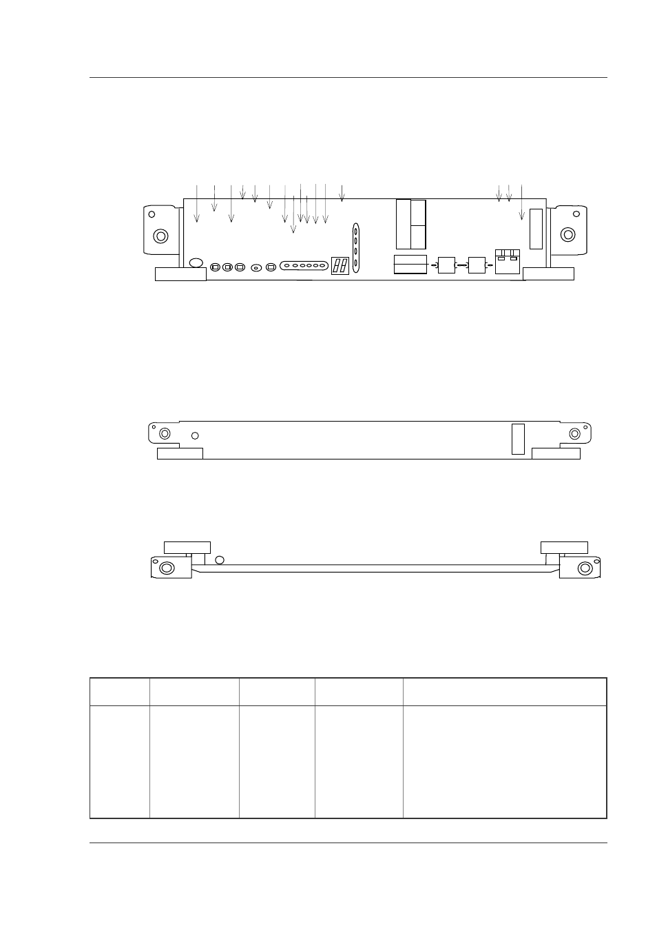
RMB-IO(H)
The RMB-IO(H) for GR2000-6H, GR2000-10H and GR2000-20H (BCU-H850H,
BCU-M850H and BCU-L850H) physically appears as Figure 3-17
Figure 3-17 RMB-IO(H) Front Panel View
3.3.8
CSW
The CSW-L3MH for GR2000-20H, and the CSW-L1M and the CSW-L3M for
GR2000-20 physically appear as Figure 3-18 and Figure 3-19. To explore the LED
display functions, see the Operations Guide.
Figure 3-18 CSW-L3MH Front Panel View
Figure 3-19 CSW-L1M and CSW-L3M Front Panel View
Switch and LED indication
Table 3-11 BCU switch and function of LED indications
Nam of
Board
Name of switch
and LED
Switch or LED
Status
Content
CSW
STATUS
(GR2000-4/10)
LED: Green/
Yellow/ Red
Shows the
operating
condition of RM.
Green: Operable operation
Yellow: Blocking and cock insertion and
removal possible.
Green blinking: Under preparation (being
started up.)
Red: Fault
Extinguished: Operation not possible
(Including the device power supply being
turned off)
56
#6
75
Ȇ
Ȏ ȏ Ȑ ȇ ȑ
4/
%*
#0
)'
3
#%
6+
8'
3
3
3
Ȉ
56
#6
75
%1
&'
Ȍ
ȋ
ȍ
3
21
9'
4
4'
#&
;
#.
#4
/
'4
41
4
3
4/
$
+1
*
%1
05
1.
'
$#
5'
6
$
#5
'
6:
)
.+
0-
#
%6
;
.+
0'
'4
4
6
4
%1
05
1.
'
45
%
'/
#
57
22
4'
55
/'
/
%#
4&
'
'
'/
#
57
22
4'
55
4'
5'
6
.#
/2
6'
56
#7
:
45
%
21
56
&+
52
#%% ȉ
24+ 4
#%% Ȋ
24+ 4
S
TA
T
U
S
CS
W
(LH)
ST
AT
U
S