Front panel leds – HP DL980 G7 User Manual
Page 8
Server component identification 8
Item
Description
20
Processor memory tray (upper)
21
Processor memory tray (lower)
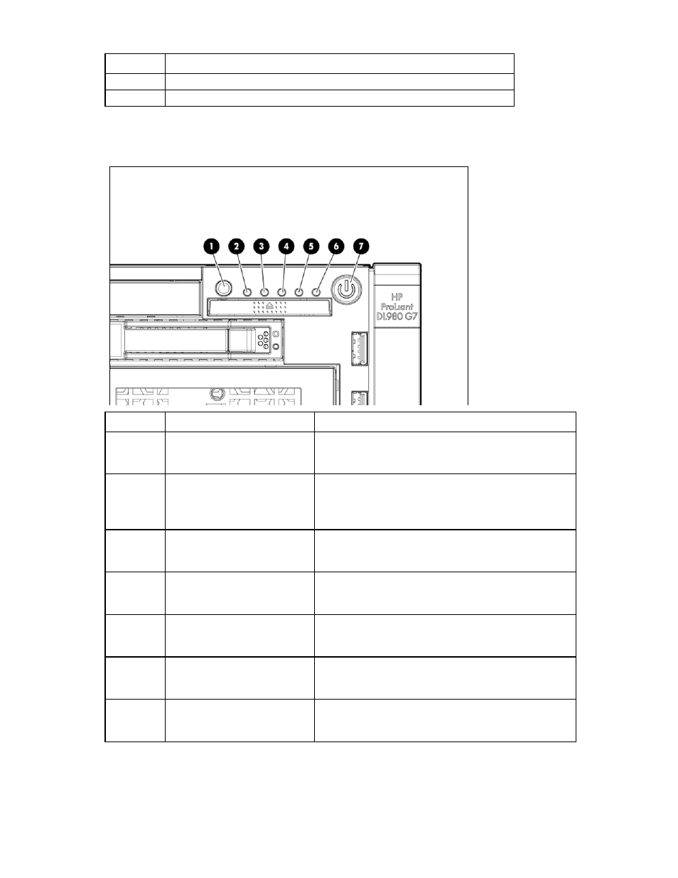
Front panel LEDs
Item
Description
Status
1
UID button and LED
Blue—Activated
Blue (flashing)—Server being managed remotely
Off—Deactivated
2
Health LED
Green—Normal (system on)
Amber (flashing)—Internal system health degraded
Red (flashing)—Internal system health critical
Off—Normal (system off)
3
NIC 1 LED
Green—Linked to network
Green (flashing)—Linked with activity on the network
Off—No network connection
4
NIC 2 LED
Green—Linked to network
Green (flashing)—Linked with activity on the network
Off—No network connection
5
NIC 3 LED
Green—Linked to network
Green (flashing)—Linked with activity on the network
Off—No network connection
6
NIC 4 LED
Green—Linked to network
Green (flashing)—Linked with activity on the network
Off—No network connection
7
Power on/Standby button and
LED
Amber—System has AC power and is in standby mode.
Green—System has AC power and is powered on.
Off—System has no AC power.