O-ring replacement, Anti-rotation clamp o-ring replacement, Front panel and interface board replacement – HP 8517B User Manual
Page 94: A1 front panel and interface board assembly
6-10
HP 8517B S-Parameter Test Set Manual
HP 8517B Test Set Replacement Procedures
Assembly Replacement Procedures
O-Ring Replacement
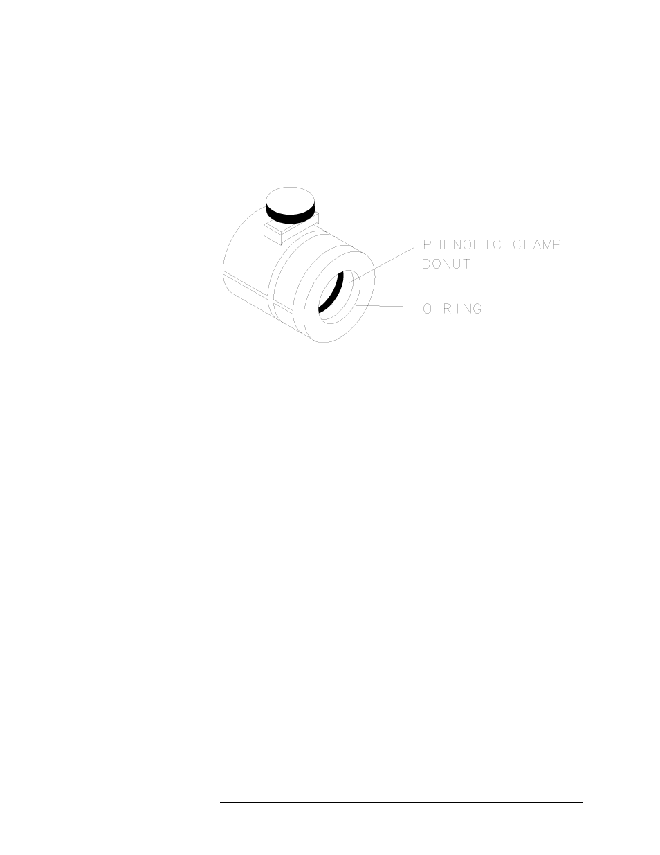
Anti-Rotation Clamp O-Ring Replacement
1. Pry the O-ring out of the clamp with fine tweezers or a similar tool.
2. To insert the new O-ring (HP part number 0900-0007), engage one side
of the ring in the slot of the phenolic clamp donut (shown in Figure 6-5).
3. Use your fingers to seat the O-ring into the groove within the clamp.
Figure 6-5
Positioning the O-Ring Within the Clamp
Front Panel and
Interface Board
Replacement
A1 Front Panel and Interface Board Assembly
1. See Figure 6-2 for component locations.
2. Remove the four semi-rigid cables that connect to the coupler on the
front panel.
3. Remove the ten screws that secure the front panel assembly to the front
frame.
4. Grasp the test ports and pull the front panel assembly out, tilting the top
of the assembly toward you.
5. Unplug the ribbon cable attached to the board assembly on the front
panel.
6. Grasp the cable attached to the line switch and carefully pull it toward
the front of the instrument. This provides enough cable length for you to
tilt the front panel assembly the rest of the way out of the test set frame.
7. Carefully remove the front panel assembly.
8. Lay the front panel assembly face down on the work surface.