Test port connector replacement, 4 mm test port connectors, Figure 6-3. diagram of 2.4 mm test port connector – HP 8517B User Manual
Page 91
HP 8517B S-Parameter Test Set Manual 6-7
HP 8517B Test Set Replacement Procedures
Assembly Replacement Procedures
Test Port Connector
Replacement
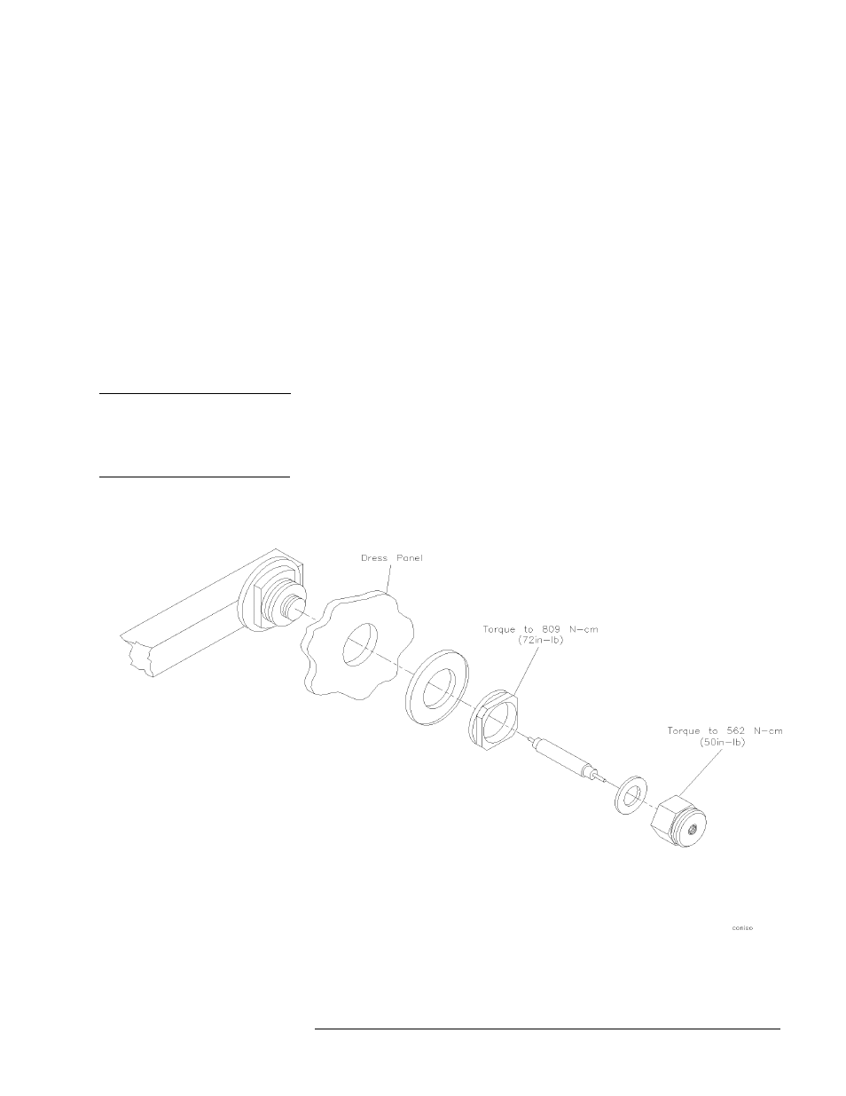
2.4 mm Test Port Connectors
1. Incline the rear of the test set approximately four inches and support it
with a stable, solid object (such as a thick book).
2. Using a 9/16-inch open-end wrench, unscrew the test port connector nut.
3. Pull out the center conductor assembly and replace it with a new
assembly. Do not touch either end of the new assembly. Part numbers for
the test port connector components are located on page 7-16.
4. Replace the test port connector nut and torque it to 562 N-cm (50 in-lb).
5. Measure the pin depth of each port using a 2.4 mm female pin-depth
gage. Refer to the connector care information in the calibration kit
manual for more information about using the gage.
NOTE
If the center pin protrudes, or if the depth is less than 0.0001 inch, remove
the connector assembly and increase or decrease shims to adjust the pin
depth to between 0.0001 and 0.0007 inch. When measuring the pin depth be
sure to include the uncertainty calculation of your gage.
6. If you added or removed shims, regage the test port connector assembly.
Figure 6-3
Diagram of 2.4 mm Test Port Connector