Fuse location, Figure 5-4. instrument hp-ib switch setting, Figure 5-5. fuse and voltage cam location – HP 8517B User Manual
Page 69
HP 8517B S-Parameter Test Set Manual 5-9
Troubleshooting the Test Set
Troubleshooting Procedures
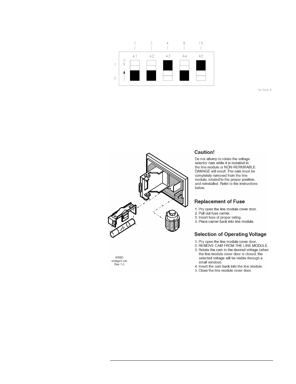
Figure 5-4 Instrument HP-IB Switch Setting
Fuse Location
The fuse is located inside the line module at the rear panel of the test set. The
value rating and part number of the fuse is listed in Chapter 7, “Replaceable
Parts” of this manual. Review the information in Figure 5-5 to replace the
line fuse or to set the voltage selector cam.
Figure 5-5 Fuse and Voltage Cam Location
Self-Test Indicators
If the front-panel ACTIVE LED (shown in Figure 5-6) fails to light within
five seconds after turning the power on, or if it lights immediately, the
instrument has failed self-test.
To determine the portion of the self-test that failed, note which LEDs on A4
board assembly are turned on. Figure 5-7 shows the location of the LEDs.
See Table 5-4 for the condition description of the LED status indicators.
- NRM42 (61 pages)
- ProLiant ML370 (49 pages)
- ProLiant ML370 (50 pages)
- ProLiant ML110 G5 (32 pages)
- PC Comm Station Pro 304251-008 (North America) (5 pages)
- 100B-TX (32 pages)
- 3C905B-TX (110 pages)
- EK-STWCT-UG. E01 (45 pages)
- 3800ux (13 pages)
- 5991-6764 (8 pages)
- LTO 4 FC (46 pages)
- StorageWorks Network Attached Storage X3000 (16 pages)
- Ultrium Drive (30 pages)
- ProLiant DL360 (49 pages)
- CD Leycom CFL-512 (5 pages)
- RDX160 (12 pages)
- 345524-B21 (54 pages)
- DT-20 (20 pages)
- SureStore 7115w (136 pages)
- HD1600 (2 pages)
- ProLiant DL160 (38 pages)
- Vectra XW (16 pages)
- D2D4004i (20 pages)
- F1588A (4 pages)
- 94500 (1 page)
- Computer Parts (21 pages)
- MSA50 (8 pages)
- 7750 (32 pages)
- Media Gateways G350 (76 pages)
- P400 Serial (9 pages)
- MSL4048 (4 pages)
- 3C590-TPO (40 pages)
- mv2040 (2 pages)
- AHA-8940 (82 pages)
- ProLiant DL385 (47 pages)
- ProLiant DL385 (174 pages)
- 5300A (19 pages)
- AMD Geode E2047551001R (111 pages)
- 1100d (102 pages)
- Reliable Transaction Router (100 pages)
- xp1024 (2 pages)
- 180 Degree Turn (24 pages)
- procurve J8165A (32 pages)
- 04H8095 (28 pages)
- 744 (154 pages)