Positioning the connector, Figure 3-6. visually aligning clamp and nut flats, Figure 3-7. mating the clamp and nut flats – HP 8517B User Manual
Page 55
HP 8517B S-Parameter Test Set Manual 3-17
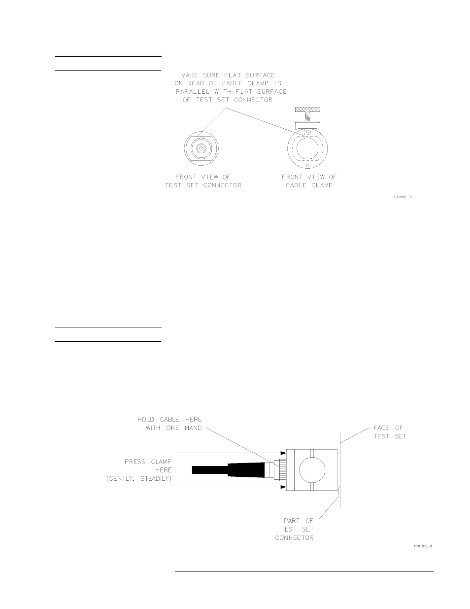
NOTE
The flats may actually be in any orientation, with respect to the front panel.
Figure 3-6
Visually Aligning Clamp and Nut Flats
Positioning the connector
See Figure 3-7. Maneuver the clamp over the RF connector and onto the test
port connector.
1. Hold the test cable with one hand. Use the other hand to press the clamp
gently and steadily, as you wiggle it into position straight over the RF
connector and onto the test port connector nut.
NOTE
Be sure to loosen the clamp when you are slipping it over the connector.
2. Fit the internal flats in the clamp over the flats on the test port connector
nut.
3. Avoid rotating the clamp as you position it so the RF connection remains
tight (remember it loosens easily).
Figure 3-7
Mating the Clamp and Nut Flats
- NRM42 (61 pages)
- ProLiant ML370 (49 pages)
- ProLiant ML370 (50 pages)
- ProLiant ML110 G5 (32 pages)
- PC Comm Station Pro 304251-008 (North America) (5 pages)
- 100B-TX (32 pages)
- 3C905B-TX (110 pages)
- EK-STWCT-UG. E01 (45 pages)
- 3800ux (13 pages)
- 5991-6764 (8 pages)
- LTO 4 FC (46 pages)
- StorageWorks Network Attached Storage X3000 (16 pages)
- Ultrium Drive (30 pages)
- ProLiant DL360 (49 pages)
- CD Leycom CFL-512 (5 pages)
- RDX160 (12 pages)
- 345524-B21 (54 pages)
- DT-20 (20 pages)
- SureStore 7115w (136 pages)
- HD1600 (2 pages)
- ProLiant DL160 (38 pages)
- Vectra XW (16 pages)
- D2D4004i (20 pages)
- F1588A (4 pages)
- 94500 (1 page)
- Computer Parts (21 pages)
- MSA50 (8 pages)
- 7750 (32 pages)
- Media Gateways G350 (76 pages)
- P400 Serial (9 pages)
- MSL4048 (4 pages)
- 3C590-TPO (40 pages)
- mv2040 (2 pages)
- AHA-8940 (82 pages)
- ProLiant DL385 (47 pages)
- ProLiant DL385 (174 pages)
- 5300A (19 pages)
- AMD Geode E2047551001R (111 pages)
- 1100d (102 pages)
- Reliable Transaction Router (100 pages)
- xp1024 (2 pages)
- 180 Degree Turn (24 pages)
- procurve J8165A (32 pages)
- 04H8095 (28 pages)
- 744 (154 pages)