HP DV3 User Manual
Page 120
4–58
Maintenance and Service Guide
Removal and replacement procedures
✎
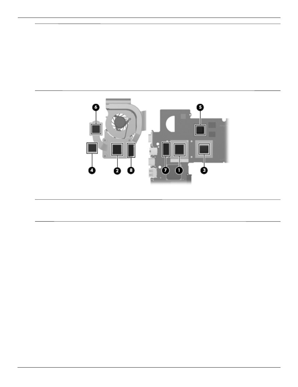
The thermal material must be thoroughly cleaned from the surfaces of the fan/heat sink assembly and the system
board each time the fan/heat sink assembly is removed:
■
Thermal paste is used on the processor 1 and the heat sink section 2 that services it.
■
Thermal pads are used on the Northbridge chip 3 and the heat sink section 4 that services it.
■
Thermal pads are used on the graphics subsystem memory module 5 and the heat sink section 6 that
services it.
■
Thermal pads are used on the other system board components 7 and heat sink sections 8 that service them.
Replacement thermal material is included with all system board, fan/heat sink assembly, and processor spare
part kits.
✎
Steps 4 and 5 apply to computer models equipped with graphics subsystems with UMA memory. See steps 2
and 3 for instructions on removing the fan/heat sink assembly on computer models equipped with graphics
subsystems with discrete memory.
4. Loosen the four captive Phillips PM2.0×7.0 screws 1 that secure the fan/heat sink assembly to the
system board.
5. Remove the fan/heat sink assembly 2.