HP DV3 User Manual
Page 107
Removal and replacement procedures
Maintenance and Service Guide
4–45
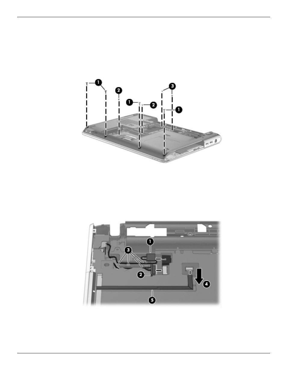
Remove the top cover:
1. Turn the computer upside down with the front toward you.
2. Remove the following screws that secure the top cover to the base enclosure:
1 Four Phillips PM2.0×8.0 screws on the front edge of the base enclosure
2 Two Phillips PM2.0×4.0 screws in the hard drive bay
3 Two Phillips PM2.0×3.0 screws on the front edge of the battery bay
3. Disconnect the power connector cable 1 from the system board.
4. Disconnect the USB board cable 2 from the system board.
5. Remove the power connector cable and USB board cable from the clips 3 built into the top cover.
6. Disconnect the caps lock LED cable 4 from the LIF connector on the system board.
7. Detach the caps lock LED cable 5 from the top cover. The caps lock LED cable is attached to the top cover
with double-sided tape.
8. Disconnect the TouchPad cable 1 from the LIF connector on the system board.
9. Disconnect the TouchPad on/off button board cable 2 from the LIF connector on the system board.
10. Release the ZIF connector 3 to which the fingerprint reader board cable is attached, and then disconnect the
fingerprint reader board cable 4 from the system board.