Hearth and Home Technologies GATEWAY User Manual
Page 33
Heat & Glo • Gateway • 288-900 Rev. W • 10/08
33
H. Screen Mesh
The screen mesh is a protective barrier and must be at-
tached.
I. Grilles and Trim
Install optional marble and brass trim surround kits as de-
sired. Marble, brass, brick, tile, or other non-combustible
materials can be used to cover up the gap between the
sheet rock and the appliance.
Do not obstruct or modify the air inlet/outlet grilles or hood.
When overlapping on both sides, leave enough space so
that the bottom grille can be lowered and the trim door
removed.
J. Hood
Install the two (2) hoods that are included with the fi re-
place. The hoods are held in place with two (2) hood clips
that are located above the glass assembly. The hoods
snap into the hood clips.
K. Shutter Settings
Figure 12.17 Glass Assembly
G. Glass Assembly
Removing Glass Assembly
Pull the four glass assembly latches out of the groove on
the glass frame. Remove glass door from the appliance
(see Figure 12.17).
Replacing Glass Assembly
Replace the glass door on the appliance. Pull out and
latch the four glass assembly latches into the groove on
the glass frame.
Handle glass doors with care.
• Inspect the gasket to ensure it is undamaged.
• Inspect the glass for cracks, chips or scratches.
• Do NOT strike, slam or scratch glass.
• Do NOT operate appliance with glass door removed,
cracked, broken or scratched.
• Replace glass door assembly as a complete appliance.
LATCHES
(BOTH BOTTOM
AND TOP)
GLASS
ASSEMBLY
NG
LP
Burner
1/4 in.
1/2 in.
WARNING
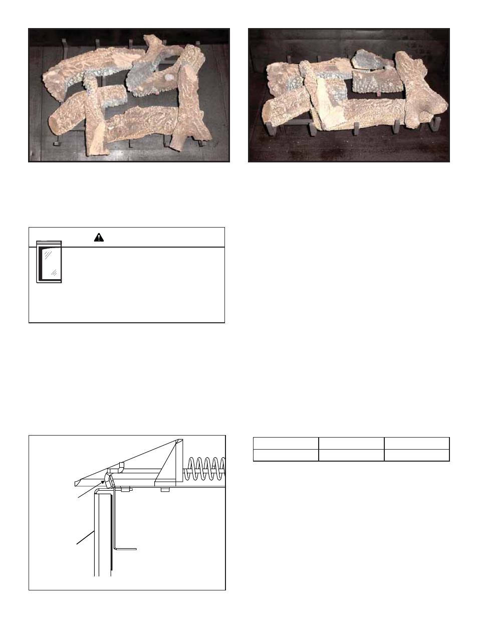
LOG #7 (SRV285-725):
Position log #7 on the locating grooves on log #3 and log #4 as shown.
7
7