Vent information and diagrams, Warning – Hearth and Home Technologies GATEWAY User Manual
Page 15
Heat & Glo • Gateway • 288-900 Rev. W • 10/08
15
5
5
Vent Information and Diagrams
Fire Risk.
Asphyxiation Risk.
This appliance requires the specifi ed pipe for
operation.
• Incorrect pipe may cause spillage, condensation
and overheating.
WARNING
Fire Risk.
Explosion Risk.
Venting parameters must not be exceeded.
This gas fi replace must never be vented by
connecting to a chimney fl ue serving a separate
solid fuel burning appliance.
WARNING
Model GATEWAY is approved to use Duravent 4-inch (102
mm) diameter B-type vent for installations that terminate
vertically. The PV-Flex Series vent pipe is approved for
use in installations that terminate horizontally. This pipe
is tested and listed as an approved component of the
fi replace.
This model may also use single wall rigid or fl exible gas
vent IF and ONLY IF the vent system is installed within
non-combustible construction such as a masonry chim-
ney. The same diameter noted above for B-type vent
must be used for single-wall vent (see Figure 5.1).
For B-type vent the clearance to combustibles is 1-inch all
around the pipe. Follow vent manufacturers REQUIRED
clearances. For PV-Flex the clearances are 1-1/2 in. top
and 1 in. sides and bottom when venting horizontally
and 1 in. on all sides when passing vertically through
combustible materials.
A. Vent System Approvals
Vent pipes must be installed within the conditioned house
envelope in order to avoid fl ue gas condensation. Verti-
cal termination through an unconditioned attic space is
permissible.
The fl ame and ember appearance may vary based on the
type of fuel burned and the venting confi guration used.
NOTE: Due to the positive pressure within the Gateway
venting system, when using PV-FLEX use a 1/2 in. bead of
HIGH TEMPERATURE silicone caulk on ALL pipe ends and
connectors throughout the vent run to ensure a completely
sealed system.
No. of 90º
Elbows/ Bends
Maximum
Vertical Run
Maximum
Horizontal Run
Maximum
Total Run
0
-
40’ (12.2 m)
40’ (12.2 m)
1
50’ (15.2 m)
-
50’ (15.2 m)
1
-
35’ (10.7 m)
35’ (10.7 m)
2
-
35’ (10.7 m)
35’ (10.7 m)
2
35’ (10.7 m)
35’ (10.7 m)
38’ (11.6 m)
3
30’ (9.1 m)
35’ (10.7 m)
35’ (10.7 m)
4
25’ (7.6 m)
32’ (9.8 m)
35’ (10.7 m)
5
25’ (7.6m)
30’ (9.1 m)
33’ (10.1 m)
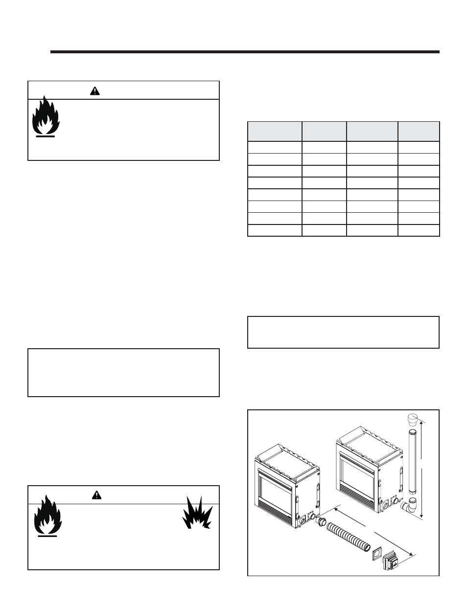
Figure 5.1 Vent System Attachment
The following fi gures are examples of approved venting
conditions. Venting downward (3 feet maximum) is ap-
proved, to allow venting below the fl oor. However, only
one downward section is allowed for up to, but not ex-
ceeding 3 feet maximum.
Maximum Total Run: = 50 FT.
Maximum No. Of Elbows/bends: fi ve - 90º or ten - 45º
50 FT.
40 FT.
B. System Components
Consult Local Building Code Offi cials and Codes for
proper vent system installations.
Plan and install the vent system using the parameters
shown in this vent system confi guration chart.
Continue to add vent components, until the vent run is
completed.
See Section 8 for instructions regarding assembly of vent
sections and securing vent sections.
Note: It is always better to fi rst attach a straight section of
vent to the unit before attaching an elbow. Avoid using elbows
in the vent system if possible.