Electrical information, Warning caution, Warning – Hearth and Home Technologies GATEWAY User Manual
Page 27
Heat & Glo • Gateway • 288-900 Rev. W • 10/08
27
C. Intellifi re Ignition System Wiring
This appliance requires a 110 VAC supply to the appliance
junction box for operation. A wiring diagram is shown in
Figure 10.2.
This appliance is equipped with an Intellifi re control valve
which operates on a 3 volt system.
This appliance is supplied with a 3 volt AC transformer,
which requires the installation of the supplied junction box.
It is highly recommended that the junction box be installed
at this time to avoid reconstruction.
A. Intermittent Pilot Ignition (IPI) System
The gas control system used with this model is Intermit-
tent Pilot Ignition (IPI). This system includes a 3V control
valve, electronic module, and intermittent pilot.
10
10
Electrical Information
Note: This appliance must be electrically wired and grounded
in accordance with local codes or, in the absence of local
codes, with National Electric Code ANSI/NFPA 70-latest
edition or the Canadian Electric Code, CSA C221.1.
B. Connecting to the Appliance
Wire 110V to electrical junction box.
Do NOT wire 110V to valve.
• Incorrect wiring will damage millivolt valves.
• Incorrect wiring will override IPI safety lockout
and may cause explosion.
Optional Accessories Requirements
Wiring for optional accessories should be done now to
avoid reconstruction.
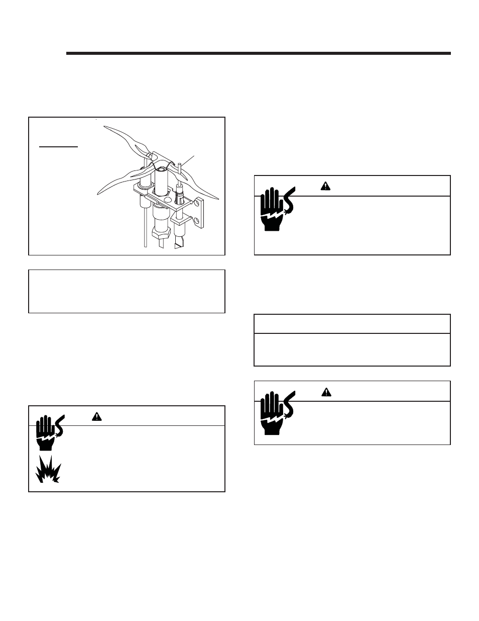
Figure 10.1
WARNING
CAUTION
Label all wires prior to disconnection when servicing controls.
Wiring errors can cause improper and dangerous operation.
Verify proper operation after servicing.
Shock hazard.
• Replace damaged wire with type 105º C rated
wire.
• Wire must have high temperature insulation.
WARNING
NOTE:
Flames too close to the ceramic
insulators can cause nuisance lock-
outs and electrode failure.
IPI IGNITION
FLAME
SENSOR
ROD
Shock hazard.
• DO NOT connect 120V directly to ignition
components.
• System failure will occur.
• Warranty will be voided.
WARNING
Wall Switch
Position the wall switch in the desired position on a wall.
Using 14 AWG or greater wire, following local codes, wire
the wall switch to the 110 VAC pigtail wires at the rocker
switch. The ground wire must be securely attached to the
ground stud in the junction box. DO NOT run 110-120
VAC to the valve. The valve system runs off 3 volts pro-
vided by the 3 volt transformer. See Figure 10.2.
• A 110-120 VAC circuit for this product must be protected
with ground-fault circuit-interrupter protection, in compliance
with the applicable electrical codes, when it is installed in
locations such as in bathrooms or near sinks.