C. install wall shield firestops – Hearth and Home Technologies GATEWAY User Manual
Page 20
Heat & Glo • Gateway • 288-900 Rev. W • 10/08
20
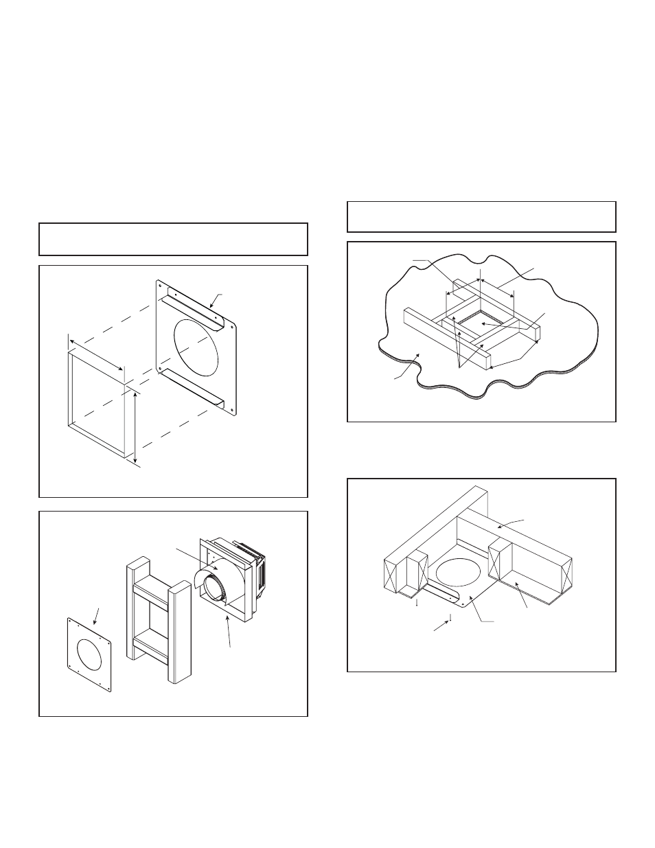
Figure 6.3 Firestop Wall Hole
Figure 6.4 Interior Wall Shield Firestop & Termination Cap
C. Install Wall Shield Firestops
For Horizontal Runs - Wall shield fi restops are REQUIRED
on both sides of a combustible wall through which the vent
passes.
To install wall shield fi restops for horizontal runs that pass
through either interior or exterior walls:
• Cut a 7 in. x 8 in. (178 mm x 204 mm) hole through the
wall.
• Position the wall shield fi restops on both sides of the
hole previously cut and secure the wall shield fi restops
with nails or screws.
• Continue the vent run through the wall shield fi restops.
TRIM HEAT SHIELD IF TOO LONG,
ADD TO SHIELD IF TOO SHORT
TERMINATION CAP
WITH BUILT-IN
EXTERIOR FIRESTOP
PV-FS
INTERIOR
FIRESTOP
Note: There must be no insulation or other combustibles
inside the framed wall shield fi restop opening.
PV-FS
FIRESTOP
7 in.
8 in.
If the area above the ceiling is NOT an attic, position and
secure the ceiling fi restop on the ceiling side of the previ-
ously cut and framed hole.
Figure 6.5 Hole & New Framing Members
CEILING
NEW
FRAMING
MEMBERS
EXISTING CEILING
JOISTS
CHIMNEY
HOLE
7 in.
178 mm
8 in.
204 mm
Figure 6.6 Ceiling Firestop (Ceiling Side)
JOIST
PV-FS
CEILING
FIRESTOP
CEILING
NAILS (4 REQUIRED)
• Mark the ceiling to establish the center point of the vent.
• Drill a hole or drive a nail through this center point.
• Check the fl oor above for any obstructions, such as wir-
ing or plumbing runs.
• Reposition the fi replace and vent system, if necessary,
to accommodate the ceiling joists and/or obstructions.
• Cut a 7 in. x 8 in. (178 mm x 204 mm) hole through the
ceiling, using the center point previously marked.
• Frame the hole with framing lumber the same size as
the ceiling joists.
Note: There must be NO INSULATION or other combustibles
inside the framed fi restop opening.
For Vertical Runs - One ceiling fi restop is REQUIRED at
the hole in each ceiling through which the vent passes.
To install fi restops for vertical runs that pass through ceilings:
• Position a plumb bob directly over the center of the ver-
tical vent component.
If the area above the ceiling IS an attic, position and se-
cure the fi restop on top of the previously framed hole. Fig-
ure 6.7 shows an attic installation. Keep insulation away
from the vent pipe at least 1 inch (25 mm).
While it is not mandatory, it is strongly recommended that
an attic insulation shield be used whenever insulation
can come in contact with the vent pipe. Follow your local
building codes.