D. vent termination – Hearth and Home Technologies GATEWAY User Manual
Page 21
Heat & Glo • Gateway • 288-900 Rev. W • 10/08
21
For Horizontal Terminations - To attach and secure the
termination cap to the last section of horizontal vent:
• Venting from the fi replace must extend through the
interior fi restop to fl ush with exterior surface.
• The termination kit should pass through the wall fi restops
from the exterior of the building.
• Adjust the termination cap to its fi nal exterior position on
the building.
• Figure 16.2 shows the approved cap and pipe for horizontal
termination. No other components may be used.
• For vent runs over 25 feet in length, a pipe connector
must be used to connect one pipe section to another
(see Figure 8.2).
Note: Due to the positive pressure within the Gateway venting
system, when using PV-FLEX use a 1/2 inch bead of silicone
caulk on ALL pipe ends and connectors throughout the vent
run to ensure a completely sealed system.
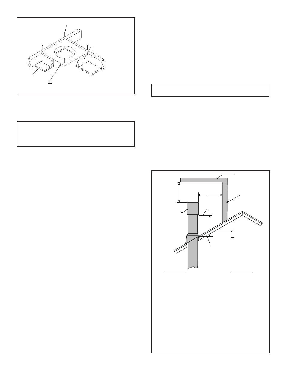
Figure 6.7 Attic Firestop
CEILING
CEILING FIRESTOP
RAFTER
NAILS OR SCREWS (4 REQUIRED)
Note: For vertical termination the termination cap must be
listed for the vent pipe used.
• Continue to install concentric vent sections up through
the roof hole (for inside vent installations) or up past the
roof line until you reach the appropriate distance above
the roof (for outside terminations).
WARNING: major U.S. Building codes specify minimum
chimney and/or vent height above the roof top. These
minimum heights are necessary in the interest of safety.
See the following diagram for minimum heights, provided
the termination cap is at least two feet from a vertical wall
and two feet below a horizontal overhang.
To seal the roof hole, and to divert rain and snow from the
vent system:
• Attach a fl ashing to the roof using nails, and use a non-
hardening mastic around the edges of the fl ashing base
where it meets the roof.
• Attach a storm collar over the fl ashing joint to form a wa-
ter-tight seal. Place non-hardening mastic around the
joint, between the storm collar and the vertical pipe.
• Slide the termination cap over the end of the vent pipe
and rotate the pipe clockwise 1/4 turn.
Roof Pitch
H (Min.) Ft.
Flat to 6/12..................................................1.0*
Over 6/12 to 7/12 ........................................1.25*
Over 7/12 to 8/12 ........................................1.5*
Over 8/12 to 9/12 ........................................2.0*
Over 9/12 to 10/12 ......................................2.5*
Over 10/12 to 11/12 ....................................3.25
Over 11/12 to 12/12 ....................................4.0
Over 12/12 to 14/12 ....................................5.0
Over 14/12 to 16/12 ....................................6.0
Over 16/12 to 18/12 ....................................7.0
Over 18/12 to 20/12 ....................................7.5
Over 20/12 to 21/12 ....................................8.0
* 3 foot minimum in snow regions
Figure 6.8 Minimum height from roof to lowest discharge
opening
Note: This also pertains to vertical vent systems installed on
the outside of the building.
HORIZONTAL
OVERHANG
VERTICAL
WALL
GAS DIRECT VENT
TERMINATION CAP
12
X
ROOF PITCH
IS X/ 12
LOWEST
DISCHARGE
OPENING
2 FT.
MIN.
20 INCHES MIN.
H (MIN.) - MINIMUM HEIGHT FROM ROOF
TO LOWEST DISCHARGE OPENING
For Vertical Terminations - To locate the vent and install
the vent sections:
• Locate and mark the vent center point on the underside
of the roof, and drive a nail through the center point.
• Make the outline of the roof hole around the center point
nail.
• The size of the roof hole framing dimensions depend
on the pitch of the roof. There MUST BE a 1 inch (25.4
mm) clearance from the vertical vent pipe to combustible
materials.
• Mark the roof hole accordingly.
• Cover the opening of the installed vent pipes.
• Cut and frame the roof hole.
• Use framing lumber the same size as the roof rafters
and install the frame securely. Flashing anchored to the
frame must withstand heavy winds.
D. Vent Termination