D. mantel projections – Hearth and Home Technologies GATEWAY User Manual
Page 12
Heat & Glo • Gateway • 288-900 Rev. W • 10/08
12
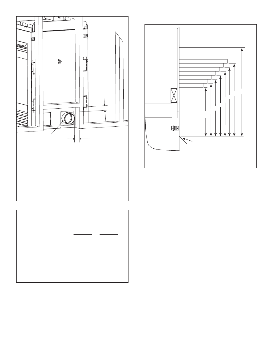
D. Mantel Projections
Figure 3.4 Clearances to mantels or other combustibles
above
appliance
CEILING
12 in.
11 in.
10 in.
9 in.
8 in.
7 in.
6 in.
36 in.
18 in.
17 in.
16 in.
15 in.
14 in.
13 in.
12 in.
TOP OF HOOD
Framing should be constructed
of 2 X 4 lumber or heavier.
EXHAUST
COLLAR
1 in. (25,4 mm)
B-Vent
1 in. (25.4 mm)
PV-FLEX
1-1/2 in. (38 mm)
NOTE: A 1 inch clearance (B-Vent) or 1-1/2 inch
clearance (PV-FLEX) must be maintained between the
top of the pipe in a horizontal configuration and any
combustible materials. Otherwise, 1 inch clearance
should be maintained between the pipe and any
combustible materials.
Figure 3.3
Minimum Clearances from the Vent Pipe to
Combustible Materials
B-Vent PV-Flex
Inches (mm)
Inches (mm)
Vertical Sections. ............... 1 (25) ............... 1 (25)
Horizontal Sections
Top ....................................... 1 (25) ......... 1-1/2 (38)
Bottom ................................. 1 (25) ............... 1 (25)
Sides.................................... 1 (25) ............... 1 (25)
At Wall Firestops
Top ....................................... 1 (25) ......... 1-1/2 (38)
Bottom ................................. 1 (25) ............... 1 (25)
Sides.................................... 1 (25) ............... 1 (25)