Names of parts, Front panel, Rear panel – Tascam MM-4D/IN-E 4-Channel Mic/Line Input Dante Converter with Built-In DSP Mixer User Manual
Page 8: Front panel rear panel, Mm-4d/in-e mm-4d/in-x
8
TASCAM MM-4D/IN-E / MM-4D/IN-X
Names of parts
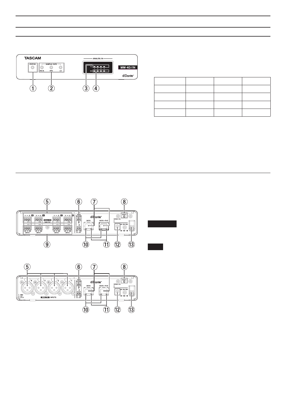
Front panel
1
STATUS indicator
The
STATUS
indicator blinks blue under the following
conditions.
o
When no LAN cable is connected
o
When the Dante module is not operating properly
2
SAMPLE RATE indicator
The lit/unlit state of the three SAMPLE RATE indicators
(44.1k, 48k and ×2) show the sampling frequency status
of the unit.
44.1 kHz
48 kHz
x2
44.1 kHz
Lit
Unlit
Unlit
48 kHz
Unlit
Lit
Unlit
88.2 kHz
Lit
Unlit
Lit
96 kHz
Unlit
Lit
Lit
3
OL indicators
These light when analog input signals overload.
4
IN SIG indicators
These light when sound is being input through the an-
alog inputs.
Input is judged to have occurred when the signal level
exceeds −60 dBFS.
Rear panel
MM-4D/IN-E
MM-4D/IN-X
5
Analog input connectors
MM-4D/IN-E
These are balanced Euroblock analog input connec-
tors. (HOT, COLD, GND from the left)
MM-4D/IN-X
These are balanced XLR analog input jacks. (1: GND,
2: HOT, 3: COLD)
6
DC IN/DC OUT connectors
The DC-IN connector is above, and the
DC-OUT
connec-
tor is below. (Left is 12V, and right is GND.)
These connectors are specifically for power daisy-chain-
ing.
ATTENTION
Disconnect the AC adapter before connecting the
DC IN
and
DC OUT
connectors.
NOTE
i
Power daisy-chaining can be enabled by connecting the
DC OUT
and
DC IN
connectors. Power daisy-chaining of
up to two units is possible
i
When powering by PoE, the first unit in the powerdai-
sy-chain will not be powered. In this case, use a dedicat-
ed PS-P1220E AC adapter (sold separately) to power the
first unit in the daisy chain.
7
DATA/DATA+PoE connectors
These are Dante transmission connectors.
Use to connect the unit to a Dante network.
Use the DATA+PoE connector when connecting to a
switching hub that supports PoE power supply. In this
case, use of an AC adapter is not necessary.
Either connector can be used when using a switching
hub that does not support PoE power supply.
8
RESET button
This resets the settings.
Press and hold for 5 seconds to reset all Dante settings.
Press and hold for 10 seconds to reset all unit settings.