Rear panel – Tascam MZ-223 - Industrial-Grade Zone Mixer User Manual
Page 9
TASCAM MZ-223
9
i
TALKOVER ON switch/indicator
Press to turn the talkover function on/off.
When the talkover function is on, the
TALKOVER
ON
indicator lights, and the levels of all input
channels are lowered automatically when sound is
input from a mic.
Use the
TALKOVER DAMP
(
y
) and
TALKOVER
TIME
(
u
) knobs to adjust the attenuation level
and response time (
MIC 1
only).
o
OUTPUT SEL switches
Use these to select the output channel stereo
buses (1–3) that receive the input signals of each
channel.
p
PFL switches/indicators
When a
PFL
switch is on (
PFL
indicator lit), the
pre-fader signal (signal before fader adjustment)
can be monitored through headphones.
a
PHONES VOLUME knob
Use this to adjust the headphone output level.
s
PHONES jack
Use this standard stereo jack to connect stereo
headphones.
Use an adapter to connect headphones with a
mini plug.
When
PFL
switches (
p
) are on, the PFL signal can
be monitored.
d
MIXING knob
Use this to mix the pre-fader and monitoring sig-
nals output to the headphones.
o
Turn all the way to the
PFL
side to monitor
channels that have their
PFL
(
p
) switches
pressed in.
o
Turn all the way to the
MONITOR
side to moni-
tor the monitoring signal.
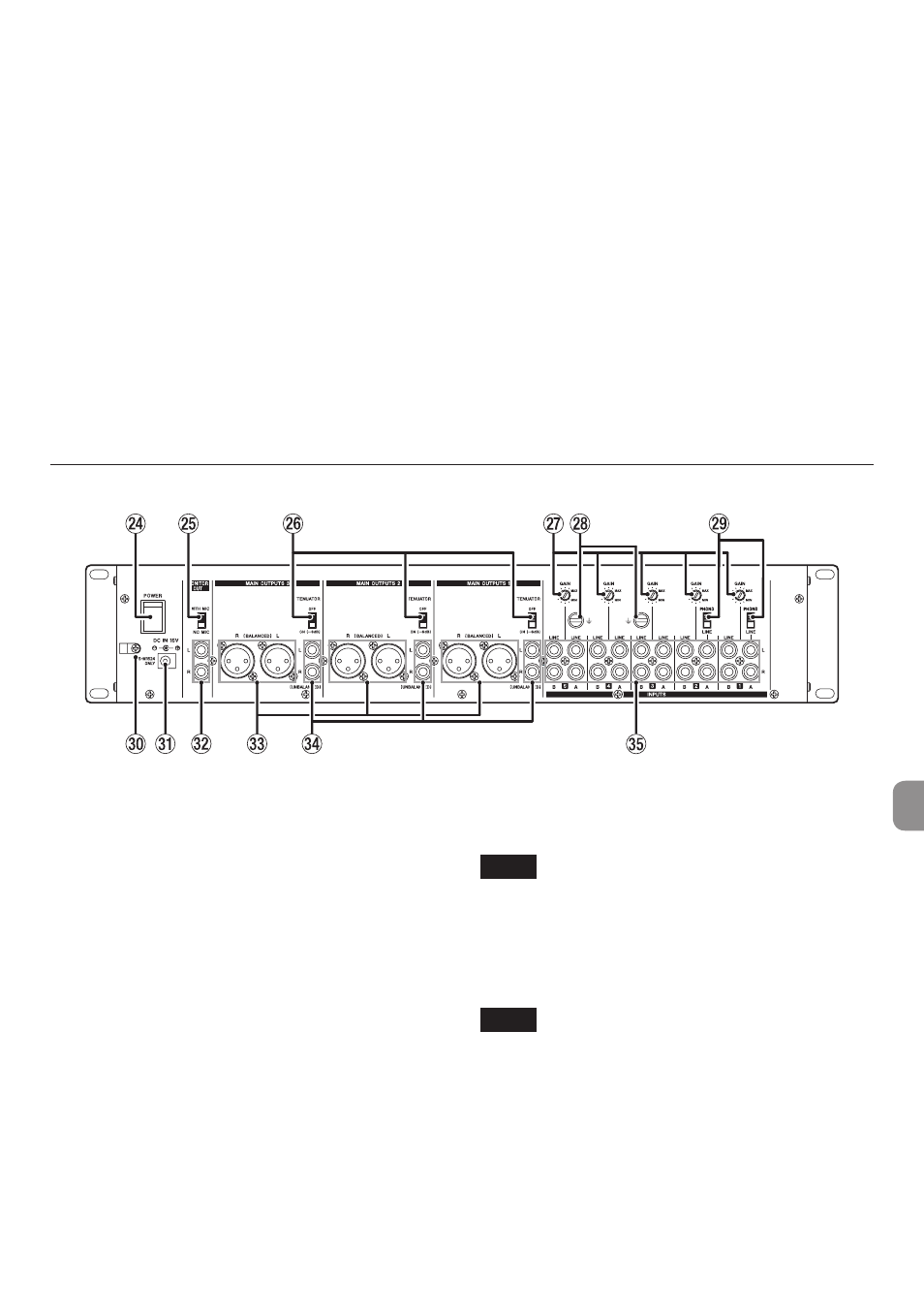
Rear panel
f
POWER switch
Press to turn the unit on and off.
When on, the
POWER
(
t
) indicator lights on the
front of the unit.
g
MONITOR OUT mic mix switch
This sets whether or not the input signals from
mics connected to the
MIC 1–2 INPUT
(
1
) jacks
on the front of the unit are sent to and mixed with
the monitoring output.
To mix the input signals from mics connected to
the
MIC 1–2 INPUT
(
1
) jacks with the monitoring
output, set the
MONITOR OUT
mic mix switch to
WITH MIC
.
h
ATTENUATOR switches
These switch the output levels from the
MAIN
OUTPUTS 1–3 (UNBALANCED)
(
v
) and
MAIN
OUTPUTS 1–3 (BALANCED)
(
c
) jacks.
Set them to
OFF
if the destination amplifier re-
ceives high gain, and set it to
ON (-6dB)
if the
destination amplifier receives low gain.
j
GAIN knobs
Use these to adjust the levels of each input chan-
nel.
NOTE
Use a small flathead screwdriver to adjust these.
k
|
(GND) connectors
If a record player is connected to the
LINE A
input
(
b
) jacks of channel 1–2, also connect its ground-
ing wire to this.
NOTE
If a humming noise occurs when connecting a
device other than a record player, connecting
a grounding wire from the metal frame of that
device (or the rack frame if rackmounted) to this
could reduce the noise.
l
LINE/PHONO input selection switches
For channels 1–2, if the output of a CD player or
similar device is connected to LINE
A
input (
b
)
jacks, set this to
LINE
. If a record player output is
connected, set it to
PHONO
.