Names and functions of parts, Front panel – Tascam MZ-223 - Industrial-Grade Zone Mixer User Manual
Page 8
8
TASCAM MZ-223
Names and functions of parts
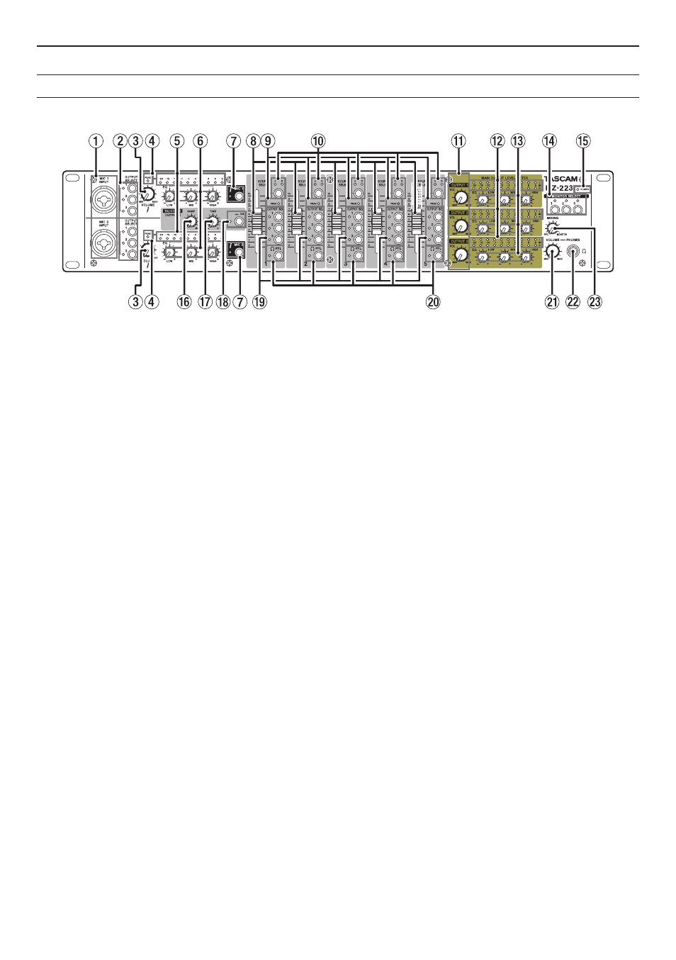
Front panel
1
MIC 1–2 INPUT jacks
These XLR/TRS combo jacks are for mic input.
2
OUTPUT SELECT switches
Use these to select outputs for audio input
through the
MIC 1–2 INPUT
jacks (
1
).
3
MIC 1–2 INPUT VOLUME knobs
Use to adjust the mic input level from the
MIC 1–2
INPUT
jacks (
1
).
4
PEAK indicators
These are mic input peak level indicators for the
MIC 1–2 INPUT
jacks (
1
).
When adjusting the
MIC 1–2 INPUT VOLUME
jack
knobs (
3
), these light just before the mic input
signals distort.
5
MIC 1–2 INPUT indicators
These are mic input level indicators for the
MIC
1–2 INPUT
jacks (
1
).
6
MIC 1–2 INPUT EQ knobs
These 3-band (HIGH/MID/LOW) equalizers adjust
the mic input sounds.
7
MIC 1–2 switches/indicators
Press to turn mic input from the
MIC 1–2 INPUT
jacks (
1
) on/off.
The
MIC 1–2
indicators light when mic input is on.
8
Channel faders
Use these to adjust the send levels of channel sig-
nals.
9
PEAK indicators
These indicators show the input peak levels of in-
put channels.
When adjusting the 1-5
GAIN
knobs (
j
) on the
back of the unit, these light just before the input
channel signals distort.
0
SOURCE SELECT switches/indicators
Use these to set the
LINE A
or
B
input jacks (
b
) on
the back of the unit as the input sources.
The indicators for the selected inputs light.
q
OUTPUT VOL knobs
Use these to adjust the output levels of the
MAIN
OUTPUTS 1–3 (UNBALANCED)
(
v
) and
MAIN
OUTPUTS 1–3 (BALANCED)
(
c
) jacks on the back
of the unit.
w
Output level indicators
These indicators show the output levels of the
MAIN OUTPUTS 1–3 (UNBALANCED)
(
v
) and
MAIN OUTPUTS 1–3 (BALANCED)
(
c
) jacks on the
back of the unit.
e
OUTPUT EQ knobs
Use these 3-band (HIGH/MID/LOW) equalizers to
adjust the sounds of the
MAIN OUTPUTS 1–3 (UN-
BALANCED)
(
v
) and
MAIN OUTPUTS 1–3 (BAL-
ANCED)
(
c
) jackson the back of the unit.
r
MONITOR SELECT switches
Use these to select the signals output from the
MONITOR OUT
(
x
) jacks.
The indicators for the selected outputs light.
t
POWER indicator
This shows the status of the unit.
When the
POWER
(
f
) switch on the back of the
unit is on, the
POWER
indicator lights.
y
TALKOVER DAMP knob
Use this to adjust the attenuation level of the talk-
over function.
u
TALKOVER TIME knob
Use this to adjust the response time of the talk-
over function.