Chapter 5 installation – EAW DSA250 & DSA230 User Manual
Page 16
additional benefits in reduced installation costs and operation. The
flexibility of the DSAPilot to automatically optimize the acoustical
performance for multiple DSA Series loudspeakers in a single larger space
further enhances their advantage over traditional solutions.
4 . 8
D e s i g n i n g D S A S y s t e m s
DSA loudspeakers can be used individually, in multiples, or in various
cluster configurations to satisfy a wide range of design requirements. By
using different configurations, DSA performance can be varied according to
the type of audio program, the frequency range for the vertical control
desired, the maximum output levels, the audience location relative to the
loudspeaker, and for meeting the requirements for special applications.
Chapter 5
Installation
This chapter details the requirements for installing the loudspeaker.
Specific details may require some variation depending on the particular
situation. However, the basic requirements are the same in all cases.
Loudspeaker refers to either a DSA230 or DSA250.
Cluster refers to any of the permissible arrangements of single or multiple
DSA230s or DSA250s as defined in DSAPilot. Whether they consist of a single
or multiple loudspeakers, all DSA clusters function as a single loudspeaker.
5 . 1 E l e c t r i c a l I n s t a l l a t i o n
This section details the electrical requirements for installing
the loudspeaker. Specific cabling details may require some
variation depending on the particular situation. However, the
basic requirements are the same in all cases.
Basic electrical installation tasks include:
Audio signal connection
Computer control connection
AC mains connection
5 . 1 . 1
C A B L E R O U T I N G C O N S I D E R AT I O N S
The configuration and orientation of the loudspeakers will determine
where signal, computer, and AC mains cabling must be connected to
the loudspeakers. For certain cluster configurations it may be necessary
to route cabling from one end of a loudspeaker to another.
The main cable routing method is to use the channels in the heat sink
extrusion that forms the rear of the DSA250 and DSA230 enclosures.
These channels are intended to be used to route and conceal cabling
the length of the enclosure as required. In this way, single wall outlet
locations for audio, computer, and AC mains can easily service a single
loudspeaker or loudspeaker cluster.
To facilitate cable routing, clusters have been arranged, where possible,
so the Power Ends of the enclosures are adjacent. This minimizes the
routing of AC mains cables, which are heavier and more difficult to
thread into the extrusion than signal cables.
16
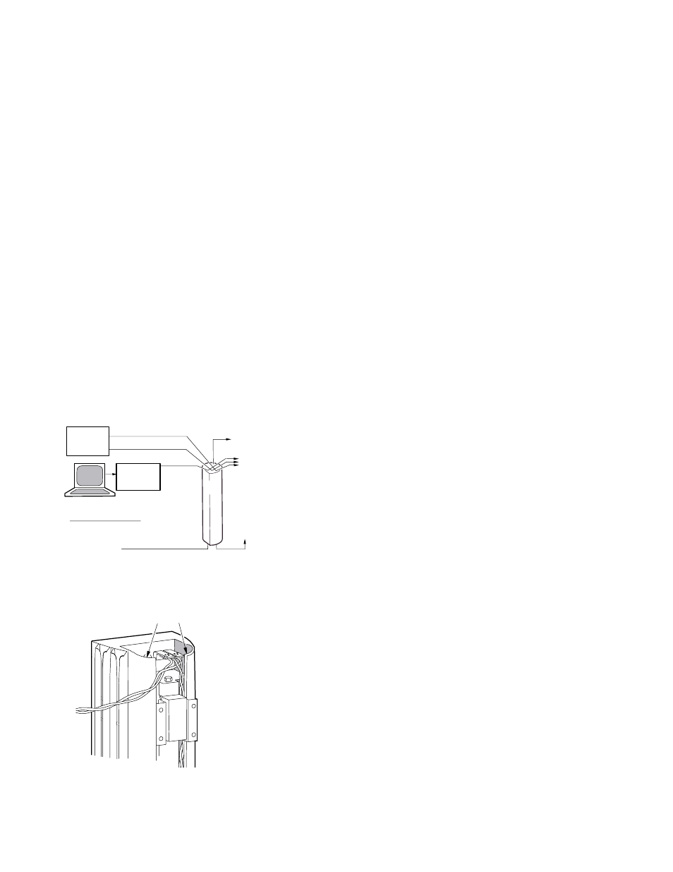
SIGNAL LINK
CABLE TO
ADJACENT DSA
LOUDSPEAKERS
SIGNAL LINK CABLE TO
ADJACENT DSA
LOUDSPEAKERS
AC MAINS*
(115V OR 230V)
TO EIA-485
CONVERTER*
EIA-485*
CABLE
AUDIO B CABLE (IF USED)*
PC*
DAISY-CHAIN
CABLE TO DSA
LOUDSPEAKERS
DSA
LINE LEVEL
AUDIO
SOURCE(S)*
RS-232
AUDIO A CABLE*
*SUPPLIED BY THE USER
Figure 5.1 Electrical Block Diagram
CABLE CHANNELS
Figure 5.1.1 Cable Channels