Installation, 1 hardware description, 1 switch front panel – PLANET SGS-5220-24P2X User Manual
Page 23
User’s Manual of SGS-5220 Series
2. INSTALLATION
This section describes the hardware features and installation of the Managed Switch on the desktop or rack mount. For easier
management and control of the Managed Switch, familiarize yourself with its display indicators, and ports. Front panel
illustrations in this chapter display the unit LED indicators. Before connecting any network device to the Managed Switch, please
read this chapter completely.
2.1 Hardware Description
2.1.1 Switch Front Panel
The front panel provides a simple interface monitoring the Managed Switch.
Figure 2-1-1
shows the front panel of the Managed
Switch.
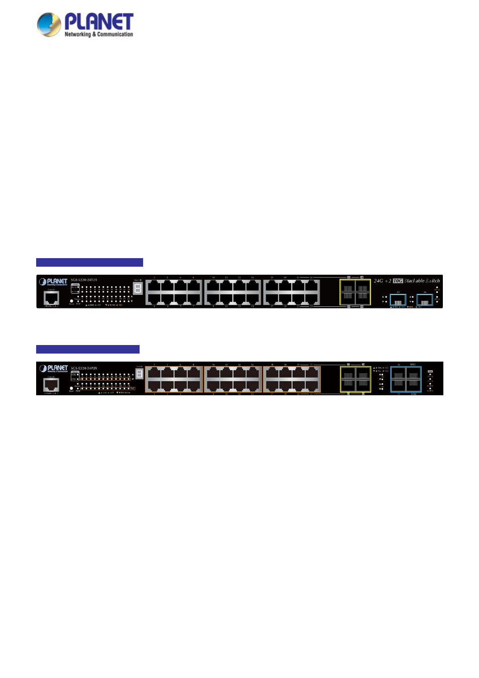
SGS-5220-24T2X Front Panel
Figure 2-1-1:
Front Panel of SGS-5220-24T2X
SGS-5220-24P2X Front Panel
Figure 2-1-1:
Front Panel of SGS-5220-24P2X
■ Gigabit TP interface
10/100/1000Base-T Copper, RJ45 twisted-pair: Up to 100 meters.
■ SFP slot
100/1000Base-X mini-GBIC slot, SFP (Small-form Factor Pluggable) transceiver module: From 550 meters to 2km
(multi-mode fiber), up to above 10/20/30/40/50/70/120 kilometers (single-mode fiber).
■ 10 Gigabit SFP+ slot
10GBase-SR/LR mini-GBIC slot, SFP+ Transceiver Module supports from 300 meters (multi-mode fiber) to up to 10
kilometers (single-mode fiber)
■ 10 Gigabit Stacked SFP+ slot
10GBase-SR/LR mini-GBIC slot, SFP+ Transceiver Module supports from 300 meters (multi-mode fiber) to up to 10
kilometers (single-mode fiber)
23