𝑇𝑜𝑡𝑎𝑙 𝐴𝑖𝑟 𝐻𝑎𝑛𝑑𝑙𝑒𝑟 𝐹𝑙𝑜𝑤, Can be calculated directly or read from table 10, 𝑵𝑺𝑶𝑷 𝑻𝑭𝑺𝑶𝑷 √ 𝑵𝑺𝑶𝑷 𝑻𝑭𝑺𝑶𝑷 – Retrotec Residential Pressure & Air Leakage User Manual
Page 48
Page 48 of 75
©Retrotec Inc. 2014
Correct Total Air Handler Flow reading to what it would be if the standard filter was in place instead of
the TrueFlow®
The flow reading on Channel B is the Total Air Handler Flow. In order to determine the actual flow, as it would
be with a standard filter in place, the Adjusted Total Air Handler Flow needs to be calculated from the Normal
System Operating Pressure (NSOP) and the TrueFlow® System Operating Pressure (TFSOP).
The easy way
With a Retrotec gauge, first set n to 0.5 using the Set Up key. Then measure the supply pressure in a stable
location under normal conditions with a clean filter. Let’s say its 121 Pa. Set Pressure on the gauge to 121 Pa
and Enter even though we aren’t going to use the gauge to control anything, this step makes the calculation that
comes next, easy. With the Flow Grid installed and Gauge set to the Flow Grid, measure the flow at say 1000
CFM on Channel B with a pressure of 100 Pa on Channel A. To get the gauge to perform the correction, press the
[@] key until the previous supply plenum pressure appears, such as “1100 CFM @121 Pa” for this example. The
flow is now corrected without any further calculations.
To confirm this calculation is correct you can set NSOP to 121 and TFSOP to 100 in the below equation. Now, do
it the easy way.
The hard way:
The Adjusted Total Air Handler Flow = √
NSOP
TFSOP
× 𝑇𝑜𝑡𝑎𝑙 𝐴𝑖𝑟 𝐻𝑎𝑛𝑑𝑙𝑒𝑟 𝐹𝑙𝑜𝑤
Eg: A total air handler flow of 1000 CFM is measured, the NSOP=75 Pa and the TFSOP =60Pa. Calculate 75/60= 1.25. Square root of 1.25 = 1.118
Multiply air handler flow of 1000 CFM by 1.118 to get an Adjusted Total Air Handler Flow of 1,118 CFM which represents the actual
system air handler flow.
√
NSOP
TFSOP
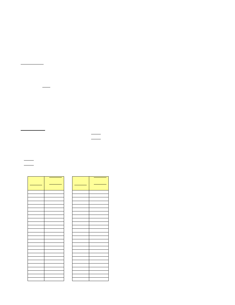
can be calculated directly or read from Table 10.
Table 10: Square roots of Normal to TrueFlow® System Operating Pressure ratios.
𝑵𝑺𝑶𝑷
𝑻𝑭𝑺𝑶𝑷
√
𝑵𝑺𝑶𝑷
𝑻𝑭𝑺𝑶𝑷
𝑵𝑺𝑶𝑷
𝑻𝑭𝑺𝑶𝑷
√
𝑵𝑺𝑶𝑷
𝑻𝑭𝑺𝑶𝑷
1.40
1.183
1.05
1.025
1.39
1.179
1.04
1.020
1.38
1.175
1.03
1.015
1.37
1.170
1.02
1.010
1.36
1.166
1.01
1.005
1.35
1.162
1.00
1.000
1.34
1.158
0.99
0.995
1.33
1.153
0.98
0.990
1.32
1.149
0.97
0.985
1.31
1.145
0.96
0.980
1.30
1.140
0.95
0.975
1.29
1.136
0.94
0.970
1.28
1.131
0.93
0.964
1.27
1.127
0.92
0.959
1.26
1.122
0.91
0.954
1.25
1.118
0.90
0.949
1.24
1.114
0.89
0.943
1.23
1.109
0.88
0.938
1.22
1.105
0.87
0.933
1.21
1.100
0.86
0.927
1.20
1.095
0.85
0.922
1.19
1.091
0.84
0.917
1.18
1.086
0.83
0.911
1.17
1.082
0.82
0.906
1.16
1.077
0.81
0.900
1.15
1.072
0.80
0.894