Measure air handler flow with a flow grid – Retrotec Residential Pressure & Air Leakage User Manual
Page 46
Page 46 of 75
©Retrotec Inc. 2014
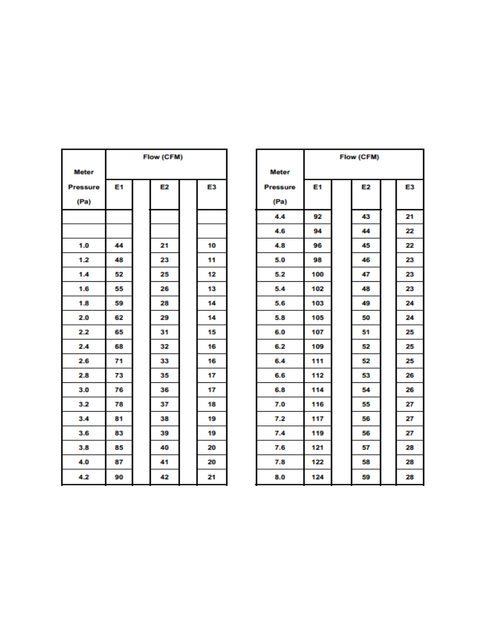
When the “Exhaust Fan Flow Meter” is set to E1, enter an area of 40.7 square inches for the “Hole Flow” Mode
because this is roughly the size of the hole in that box and has been verified to give the same results as the table
above. If you change hole size on the “Exhaust Fan Flow Meter”, change the area in the gauge to match:
1. E1 setting, Enter 40.7 square inches
2. E2 setting, Enter 19.3 square inches
3. E3 setting, Enter 9.4 square inches
Table 9: Manufactured Flow Meter Pressure-Flow Look-up
5.2.7. Measure air handler flow with a Flow Grid
Temporarily replacing the filter in the air handler distribution system with a grid containing holes of a known size
while the air handler is running allows measurement of the airflow being produced by the air handler. If the
filter location is directly adjacent to the air handler, the process will measure the total air handler flow. If the
filter is located remotely at a central return, the process will measure airflow through the central return.
The Retrotec gauge can be used with the TrueFlow® Air Handler Flow Meter built by The Energy Conservatory to
measure the system air flow using the reading from the Grid and the operating pressure.