Retrotec Residential Pressure & Air Leakage User Manual
Page 44
Page 44 of 75
©Retrotec Inc. 2014
1. Connect the red tube to the “Ref A” (red) port and send the tube outside. The “Input A” (blue) port
should remain open to the main body of the house.
2. To monitor the pressure in the room as well, connect the green tube to the “Input B” (green) port
and put the other end of the tube under the bedroom door. Keep the “Ref B“ (yellow) port open to
the main body of the house.
3. Turn on the air handler and close the bedroom door. Record the pressure changes that occur after
closing the bedroom door. Channel A will show the pressure difference between the main body of
the house and the outdoors, while Channel B will measure the pressure difference between the
main body of the house and the bedroom.
4. If the pressure in the main body of the house changes by 1 Pa or more (in either direction), consider
pressure relief measures.
5.2.4. See if the house or any room gets pressurized when all Interior Doors are
closed
Similar to the closed bedroom door test, this test looks at the pressure imbalances created when all interior
doors are closed.
1. Set up the gauge to measure building pressure with respect to outside (red tube outside, blue port
open). Take note of the pressure in the house with respect to outdoors.
2. Close all interior doors and turn on the air handler. Record the pressure change in the main body of
the house. If the pressure changes by more than 2 Pa, consider pressure relief measures.
You can also measure the pressures induced by the air handler in each room by connecting the red tube to the
gauge “Ref A”. Slide the end of the red tube under each door in turn to see the difference in pressure between
the room and the main body of the house. Consider pressure relief measures if pressure differences exceed 3
Pa with respect to the main body.
This is often done for combustion appliance rooms to detect the potential for back drafting and spilling of
combustion gases into the house.
5.2.5. See how much air is flowing out through the household Exhaust Fan
The Retrotec gauge can be used to measure the amount of air flowing through a hole. This feature enables the
gauge to be used as an Exhaust Fan Flow Meter, by simply cutting a couple of holes in a cardboard box. The
open end of the flow box should have rough dimensions which are at least two times the register dimensions,
and the depth of the box should be at least the average of the other two dimensions.
To create an Exhaust Fan Flow Meter
1. Cut a hole in one side of a medium-sized cardboard box where it is only one
layer thick, and leaving about one inch of cardboard around the edge for
stiffness.
2. Cut a 2" x 2" square hole in the center of the other side of the box, again
where the cardboard is only one layer thick. This is the flow measuring hole.
For accuracy, the small hole should be at least 1.5 inches from the edge of the
box and its area should be less than half the area of the end of the box.
3. Tape any cracks in the other sides of the box to prevent air from leaking.
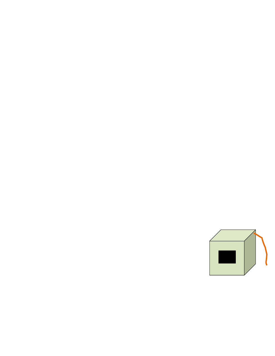
4. Punch a 0.25 inch diameter hole near a corner of the open end of the box for the pressure tube.
Insert a tube in the hole.
5. Connect the tube to the “Ref B” (yellow) and "Input A" (blue) ports of the gauge using a T connector.
6. Fit the box over the exhaust fan grille while it is running, and seal in place around the box edges.
7. Observe the pressure in the box on “PrA”. The same pressure will show on “PrB” if “Mode” is set to
Pressure.
Figure 18: Exhaust fan flow
meter