Ethernet / profinet interbus profibus – Multi-Contact MA213-04 User Manual
Page 4
Advanced Contact Technology
4 / 8
www.multi-contact.com
B
S
Ethernet / Profinet
Interbus
Profibus
7
6
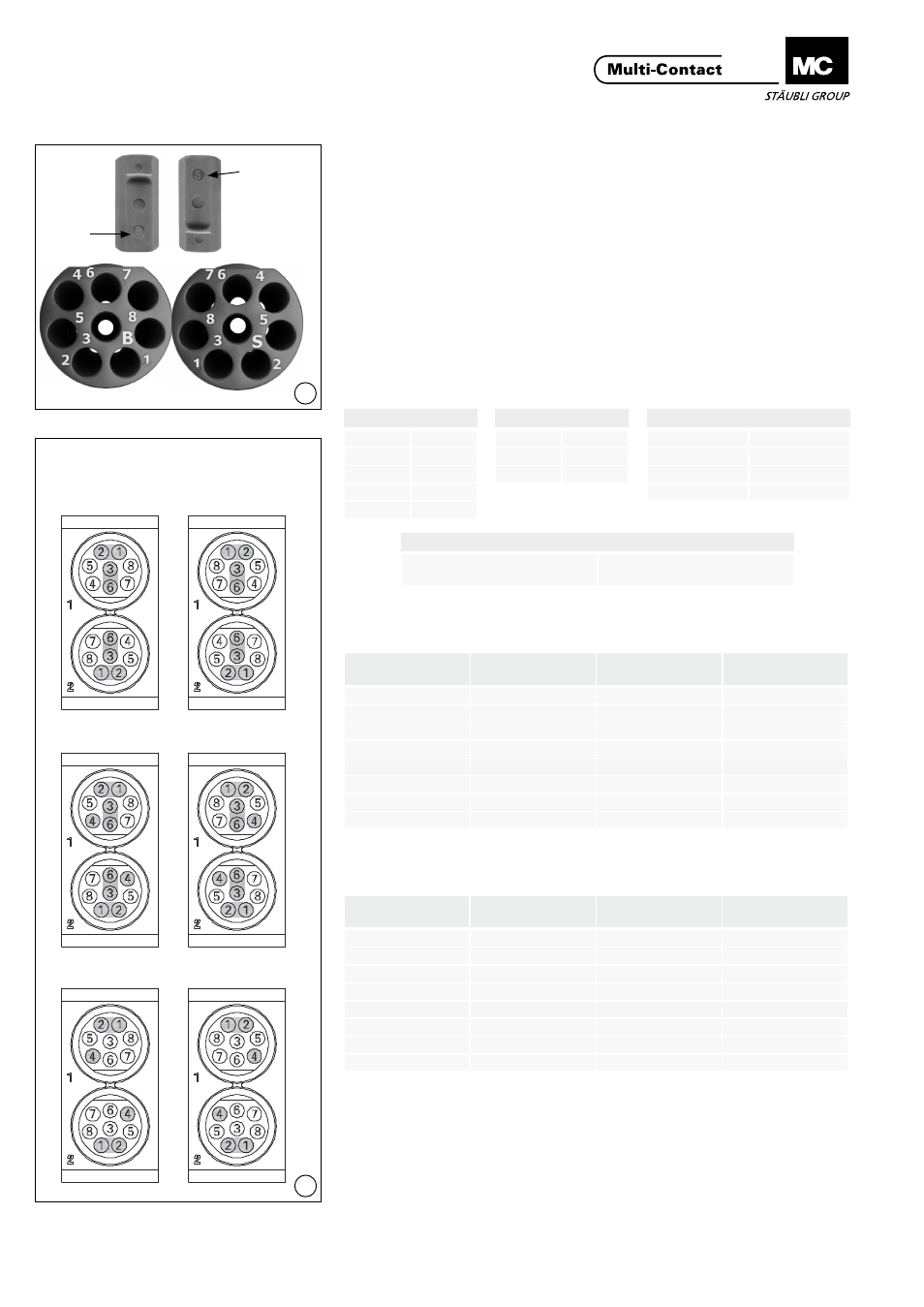
Montaje de los contactos en
la matriz
Contact assembly in inserts
(ill. 6)
La matriz hembra viene marcada
con una B, y la matriz macho con
una S. Los números de contacto se
encuentran en la cara posterior� Los
contactos se introducen desde la cara
posterior�
(ill. 6)
The female insert is marked with a B,
the pin insert is marked with an S� The
contact numbers are on the back side�
The contacts will be inserted from
back side�
Distribución de los contactos
de carga
Contact arrangement of the
contact carrier
(ill. 7)
(Visto desde los terminales)
(ill. 7)
(Seen from the termination side)
Configuración con 4 pares T568A
Configuration with 4 pairs T568A
Configuración con 4 pares T568B
Configuration with 4 pairs T568B
Lado macho
Lado hembra
Pin side
Socket side
Interbus
DO
1
/DO
2
DI
3
/DI
6
COM
4
Profibus
Line A
1
Line B
2
GND
4
Ethernet & Profinet
TX+
1
TX-
2
RX+
3
RX-
6
CANbus
Configuración individual según
las especificaciones del BUS
Individual configuration accor-
ding to BUS specifications
Contacto No.
Contact No.
Par No.
Pair No.
Color
Colour
1
1
blanco/verde
white/green
2
1
verde
green
3
2
blanco/naranja
white/orange
4
3
azul
blue
5
3
blanco/azul
white/blue
6
2
naranja
orange
7
4
blanco/marrón
white/brown
8
4
marrón
brown
Tab. 2
Tab. 3
Contacto No.
Contact No.
Par No.
Pair No.
Color
Colour
1
1
blanco/naranja
white/orange
2
1
naranja
orange
3
2
blanco/verde
white/green
4
3
azul
blue
5
3
balnco/azul
white/blue
6
2
verde
green
7
4
blanco/marrón
white/brown
8
4
marrón
brown