Removing the cr motor assembly – Epson FX-870/1170 User Manual
Page 91
Disassembly
and Assembly
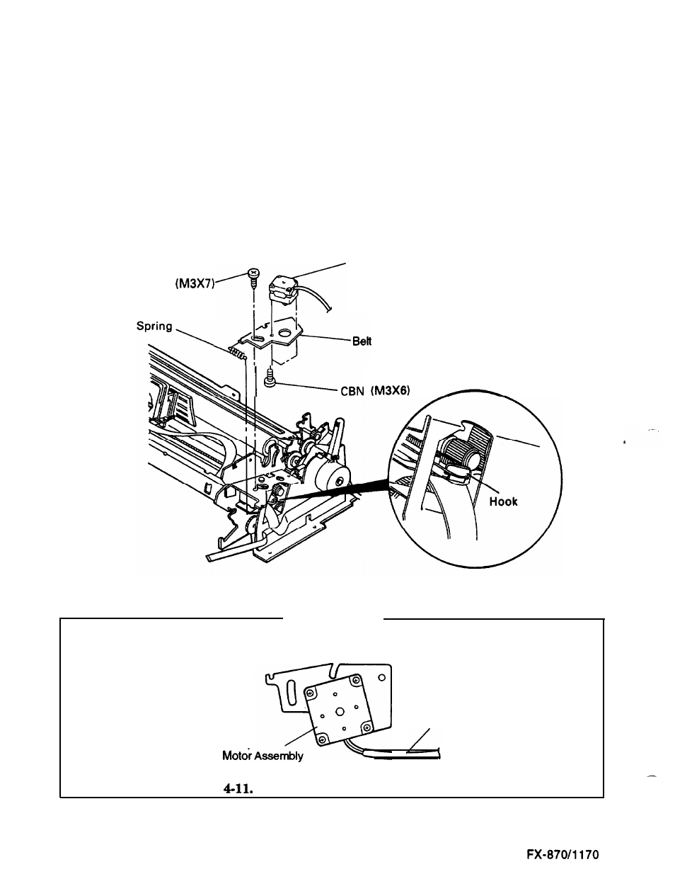
Removing the CR Motor Assembly
1.
Remove the paper guide assembly, ribbon, top cover, front cover, paper eject cover, and tractor
- ’
unit. (See page 4-5.)
2.
Remove the panel unit. (See page
4-6.)
3.
Remove the upper housing assembly. (See page 4-8.)
4.
Remove the face screw (M3x7) securing the CR motor assembly. After releasing the tension
spring, disengage the timing belt from the CR motor assembly and hang it on the hook.
5.
Disconnect connector CN13 on the C094 MAIN board assembly. Remove the CR motor
assembly.
6.
Remove
the two CBN (M3x6) screws on the back of the CR motor assembly. Remove the CR
motor assembly.
Face Screw
CR Motor Assembly
Tension Plate
Figure 4-10. Removing the CR Motor Assembly
Assembly Note
Position the CR motor assembly on the belt tension plate correctly as shown below.
CR
Cable
Figure
Positioning the CR Motor Assembly
4-12
Epson
- Stylus Pro 7800 (11 pages)
- Stylus Pro 4000 (49 pages)
- Stylus Photo R300 (2 pages)
- Stylus Pro 7000 (147 pages)
- AcuLaser C3000 (316 pages)
- Stylus Pro 7900 (24 pages)
- Stylus Pro 4450 (21 pages)
- 1000 (272 pages)
- T034120 (4 pages)
- T580300 (4 pages)
- 300 (91 pages)
- B 510DN (190 pages)
- B 510DN (218 pages)
- Stylus NX510 (8 pages)
- Stylus Photo RX580 (95 pages)
- T549300 (4 pages)
- B 500DN (168 pages)
- AculaserCX11NF (5 pages)
- 480SXU (24 pages)
- 4500 (317 pages)
- STYLUS RX500 (99 pages)
- 2100 (13 pages)
- Stylus NX215 (2 pages)
- T098320 (4 pages)
- T041020 (4 pages)
- R210 (8 pages)
- All-In-One Stylus Photo RX600 (164 pages)
- 777I (53 pages)
- T033120 (4 pages)
- Stylus CX7000F (8 pages)
- 60 (113 pages)
- T034220 (4 pages)
- WorkForce 40 Series (36 pages)
- T054220 (4 pages)
- Stylus CX3200 (11 pages)
- Stylus CX7800 (18 pages)
- T060220 (4 pages)
- 2500 (180 pages)
- AcuLaser CX11N (4 pages)
- AcuLaser CX11N (32 pages)
- 2000P (16 pages)
- T606600 (4 pages)
- Stylus CX6000 (18 pages)
- FS-4000DN (2 pages)
- MSDS T544700 (4 pages)