Epson FX-870/1170 User Manual
Page 55
Troubleshooting
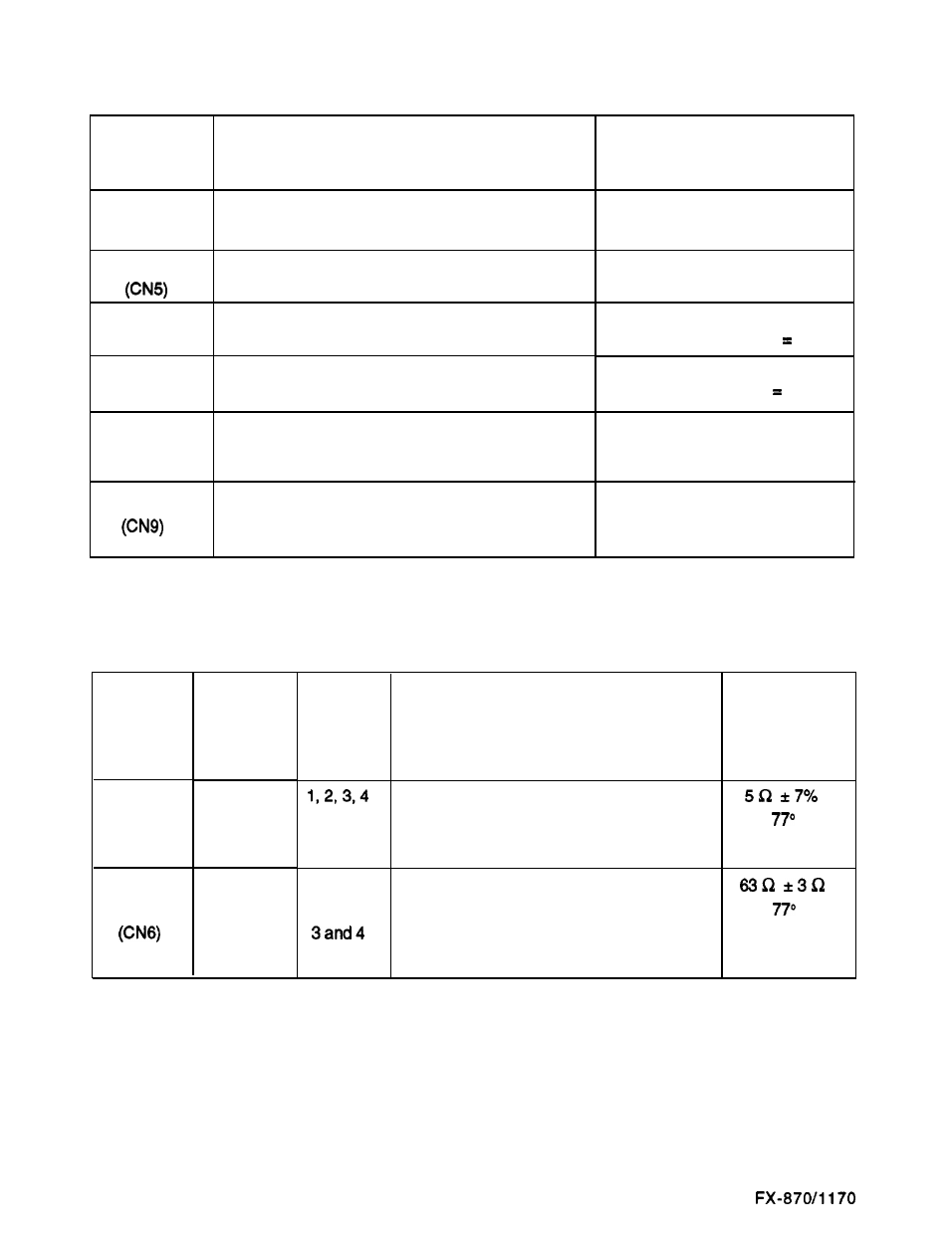
Table 3-2. Sensor Test Points
Sensor
Test Method
Connector
(Set Meter to Ohms.
Number
Check with Printer Power Off.)
Release Lever
Place one lead on each pin. Change the release
(CN4)
lever position.
Platen Gap
Place one lead on each pin. Change the adjust
lever position.
CR Home
Place one lead on each pin. Move carriage to and
(CN7)
away from home position.
Front PE
Place one lead on each pin. Toggle sensor by
(CN3)
inserting and removing paper.
Sensor
Test Method
Connector
(Set Meter to Volts.
Number
Check with Printer Power On.)
Rear PE
Place one lead on pin 3 (GND) and one on pin 2
(PER). Toggle by inserting and removing paper.
Note: Illustrations later in this chapter show sensor locations.
Motor
Connector
Number
Carriage
Motor
(CN13)
Paper Feed
Motor
Meter Reading
Meter should toggle between
open and short.
Meter should toggle between
open and short.
Meter should toggle between
open and short. (Closed active.)
Meter should toggle between
open and short. (Open active.)
Meter Reading
Meter should toggle between 0 V
and HIGH.
Table 3-3. Motor Test Points and Coil Resistance
Common
Pin
Numbers
5
6
5
Test Pin
Numbers
1 and2
Test Method
(Set Meter to Ohms. Disconnect
Motor from Main Board and Check
it with Printer Power Off.)
Meter Reading
Place one lead on pin 5 and the other lead
on each of the four test pins to check the
(at
F,
four motor phases.
25” C)
Put one lead on pin 6 and the other lead
on pin 1 and then on pin 2.
(at
F,
Put one lead on pin 5 and the other lead
25” C)
on pin 3 and then on pin 4.
Notes:
l
Common pins may be reversed. If you do not obtain the proper reading with one common, try
the other common for that motor. If you still do not obtain proper readings, the motor is bad.
l
If any phase of the motor is shorted, see Table 3-6 to check the main board. (If the drivers on
the main board are also shorted, and the board is not replaced at the same time as the motor,
the short in the main board drivers may burn out the new motor.)
3-2
E p s o n