Control circuit operation, Control circuit operation overview – Epson FX-870/1170 User Manual
Page 137
Principles of Operation
Control Circuit Operation
The control circuit consists of two circuit boards: the CO94 MAIN (main control circuit board) and
the CO94 PNL (control panel circuit board). This section describes the operation of these boards.
Control Circuit Operation Overview
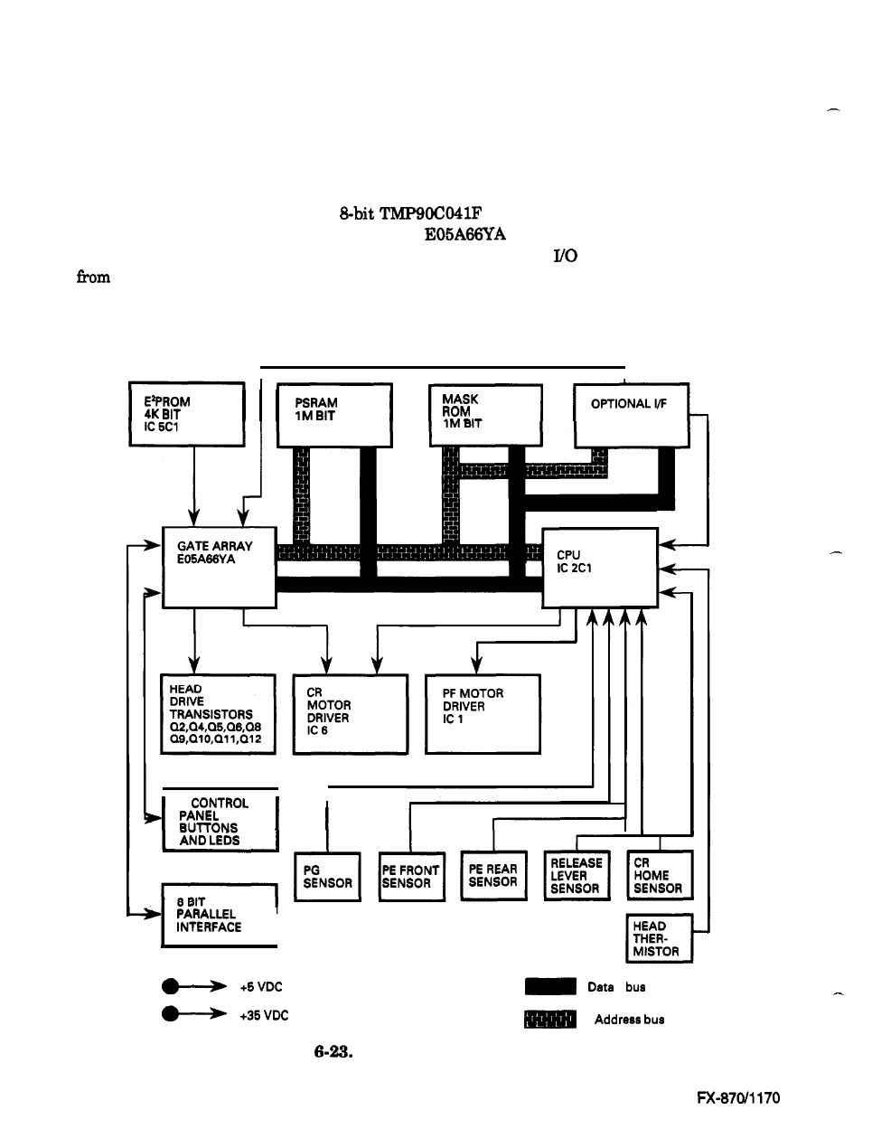
The CPU on the CO94 MAIN is an
microprocessor (9.83 MHz). It oversees
control of all the components of the printer. The
gate array contains various memory
management functions that control the memory assignment and
areas. The output signals
each detector are sent to the analog input port of the CPU. The signals from the control panel
are sent to the gate array, which in turn, sends LED signals to the control panel. The two motors
(CR and PF) are controlled by signals sent from the stepping motor control port of the CPU. Figure
6-23 shows the control circuits in block diagram form.
I
I
I
Figure!
Control Circuit Block Diagram
Epson
6-22
- Stylus Pro 7800 (11 pages)
- Stylus Pro 4000 (49 pages)
- Stylus Photo R300 (2 pages)
- Stylus Pro 7000 (147 pages)
- AcuLaser C3000 (316 pages)
- Stylus Pro 7900 (24 pages)
- Stylus Pro 4450 (21 pages)
- 1000 (272 pages)
- T034120 (4 pages)
- T580300 (4 pages)
- 300 (91 pages)
- B 510DN (190 pages)
- B 510DN (218 pages)
- Stylus NX510 (8 pages)
- Stylus Photo RX580 (95 pages)
- T549300 (4 pages)
- B 500DN (168 pages)
- AculaserCX11NF (5 pages)
- 480SXU (24 pages)
- 4500 (317 pages)
- STYLUS RX500 (99 pages)
- 2100 (13 pages)
- Stylus NX215 (2 pages)
- T098320 (4 pages)
- T041020 (4 pages)
- R210 (8 pages)
- All-In-One Stylus Photo RX600 (164 pages)
- 777I (53 pages)
- T033120 (4 pages)
- Stylus CX7000F (8 pages)
- 60 (113 pages)
- T034220 (4 pages)
- WorkForce 40 Series (36 pages)
- T054220 (4 pages)
- Stylus CX3200 (11 pages)
- Stylus CX7800 (18 pages)
- T060220 (4 pages)
- 2500 (180 pages)
- AcuLaser CX11N (32 pages)
- AcuLaser CX11N (4 pages)
- 2000P (16 pages)
- T606600 (4 pages)
- Stylus CX6000 (18 pages)
- FS-4000DN (2 pages)
- MSDS T544700 (4 pages)