Sensor circuits – Epson FX-870/1170 User Manual
Page 141
Principles of Operation
Sensor Circuits
The
printer has the following sensors: CRHOME, PE (FRONT), PE (REAR), PG
(platen gap), RELEASE
and HEAD TEMPERATURE. All the sensors are mechanical
switches, except the rear PE sensor, which is a photo diode, and the HEAD TEMPERATURE
sensor, which is a thermistor.
In addition to the sensor circuits, a
V monitor circuit and a Vref circuit are
provided. The
V monitor circuit sets the pulse length of the head drive signal. If the voltage of the
V line
drops below approximately
V, the printer stops printing for a while. As soon as the voltage
recovers, the printer starts to print at halfspeed. (The PF motor also slows down.) The Vref circuit
supplies the reference voltage for the
convertor in the CPU.
The CPU constantly monitors the printhead temperature. If the printhead temperature exceeds
the maximum level, the printer stops printing until the temperature drops to a certain level. When
the printhead temperature cools down, the printer resumes printing automatically.
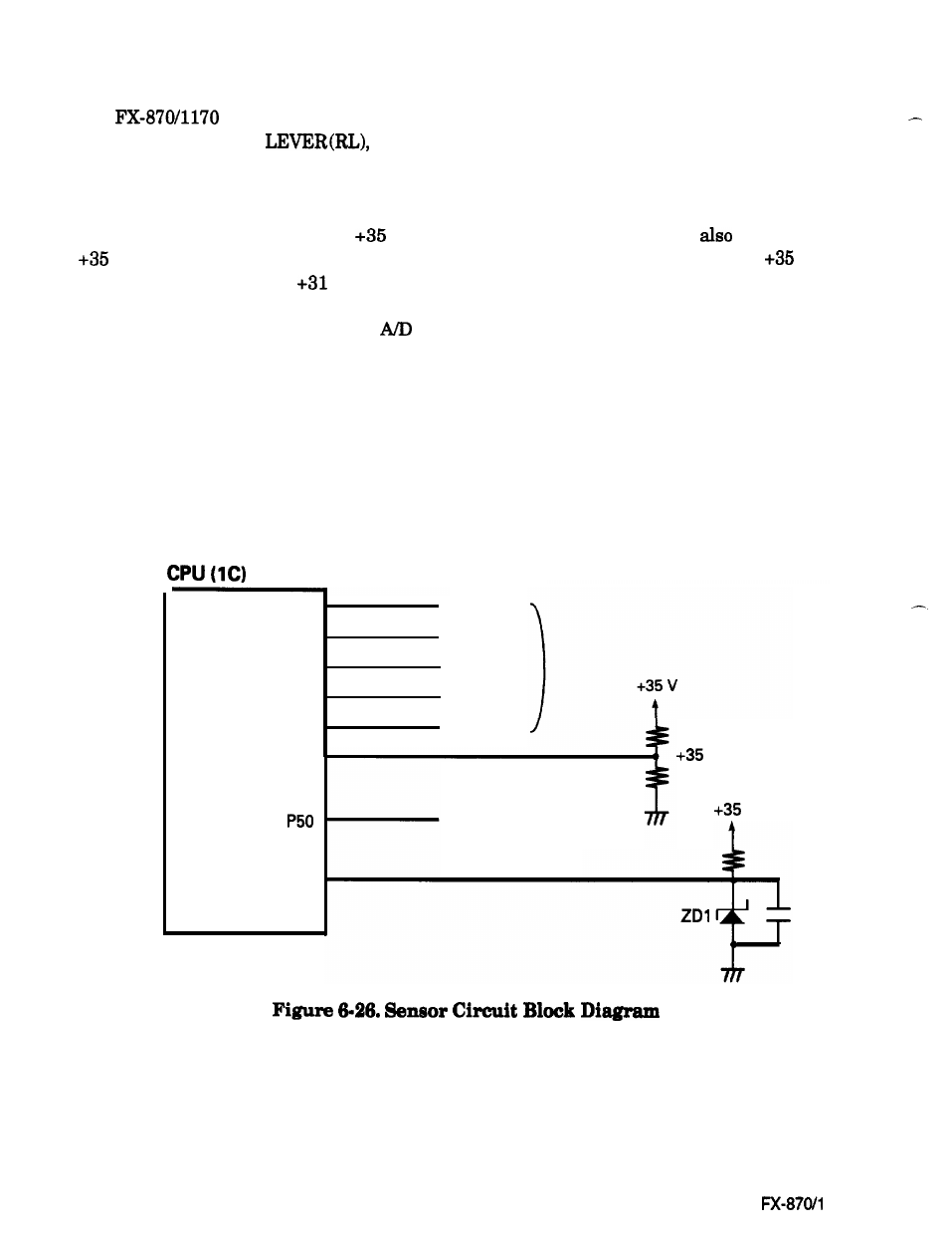
Figure 6-26 shows the sensor circuit block diagram.
P55
P52
P53
P34
P31
CRHOME
PE FRONT
PE REAR
PG
RELEASE
LEVER
P51
P51
Vref
Vref
Head Temperature
Head Temperature
Voltage Monitor
Voltage Monitor
v
v
Vref
Vref
6-26
Epson
170