Epson FX-870/1170 User Manual
Page 156
Reference Materials
See Table 1-14 for
(Centronics interface) signal functions and pin assignments.
Table 7-2. CN2, Optional
Table 7-3. CN3, Front PE Sensor
(CO64 MAIN Hoard Assembly)
(CO94 MAIN Hoard Assembly)
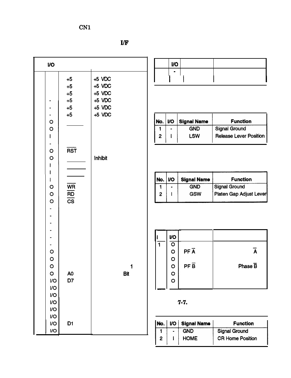
No.
I I
Signal Name
Function
1
2
3
4
5
6
7
8
9
10
11
12
13
14
15
16
17
18
19
20
21
22
23
24
25
26
27
28
29
30
31
32
33
34
35
36
TXD
READY
RXD
NC
INH
CMREQ
WRRDY
RDREQ
GND
GND
GND
GND
GND
GND
A3
A2
Al
D6
D5
D4
D3
D2
DO
Transmit Data
Ready to Receive Data
Receive Data
No Connection
Reset
Command Request
Wriie Ready
Read Request
Write
Read
Chip Select
Signal Ground
Signal Ground
Signal Ground
Signal Ground
Signal Ground
Signal Ground
Address Bus Blt 3
Address Bus Bit 2
Address Bus Bit
Address Bus 0
Data Bus Bit 7
Data Bus Bit 6
Data Bus Bit 5
Data Bus Bit 4
Data Bus Bit 3
Data Bus Bit 2
Data Bus Bit 1
Data Bus Blt 0
No.
Signal Name
Function
1
GND
Signal Ground
2 I PEF
Front Paper End
Table 7-4. CN4, Release Sensor
(CO94 MAIN Hoard Assembly)
Table 7-5. CN5, PG Sensor
(CO94 MAIN Hoard Assembly)
MO.
2
3
4
5
6
Table 7-6. CN6, Paper Feed Motor
(CO64 MAIN Hoard Assembly)
Signal Name
Function
P F A
PF Motor Phase A
PF Motor Phase
P F B
PF Motor Phase B
PF Motor
PFCOM
PF Motor Common
PFCOM
PF Motor Common
Table
CN7, Home Position Sensor
(CO64 MAIN Hoard Assembly)
Epson FX-870/1170
7-3