Reset circuit – Epson FX-870/1170 User Manual
Page 140
Principles of Operation
Reset Circuit
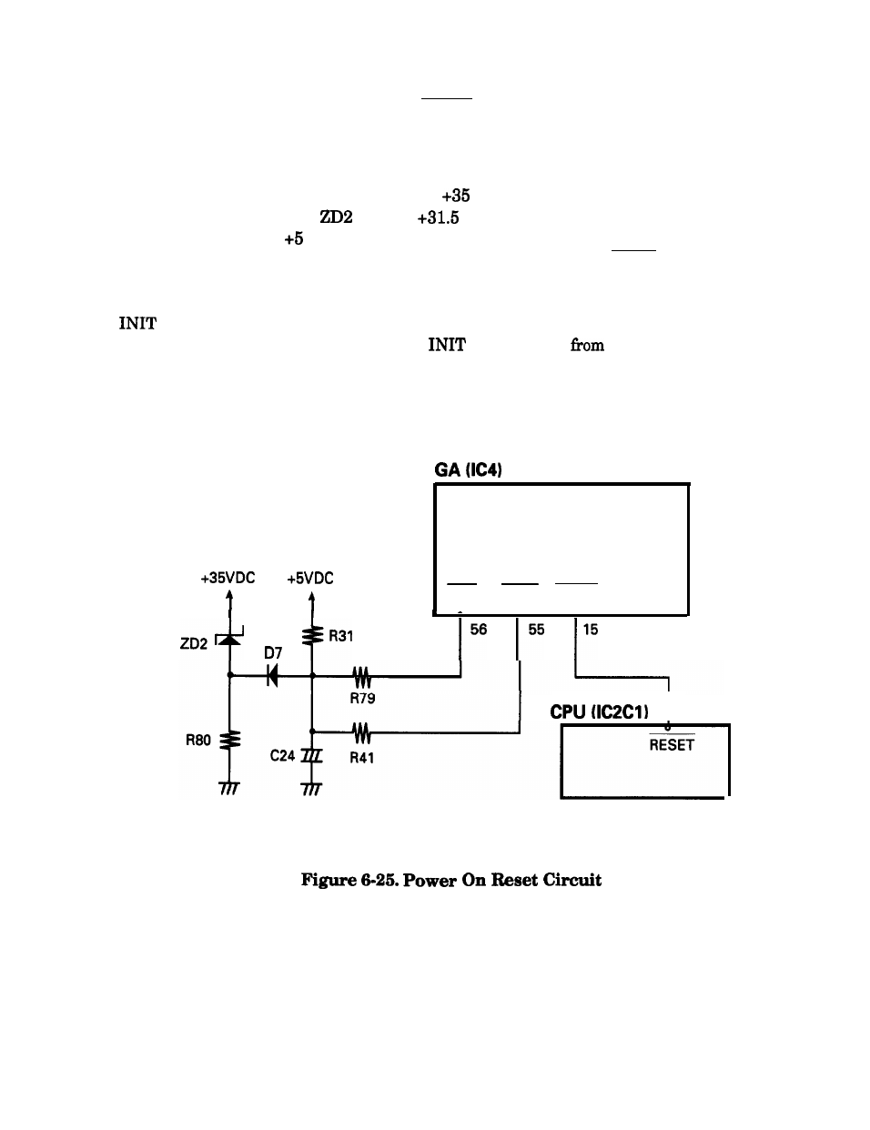
The control circuits are initialized when the RESET signal is issued. The reset operation occurs
under these two conditions:
1. Power on reset
Immediately after the power is turned on,
VDC is rapidly generated. Because it takes a
moment for the voltage at
to reach
V, the voltage at the DISC terminal on the gate
array does not reach VDC until capacitor C24 is fully charged. A similar integration circuit
is provided in the gate array and further delays the output of the ROUT signal. This LOW
level is used as a reset signal.
2.
signal reset
The reset signal is also issued when the
signal is sent
the host computer.
Figure 6-25 shows the power on reset circuit.
RIN
DISC ROUT
I 15
Epson FX-870/1170
6-25
See also other documents in the category Epson Printers:
- Stylus Pro 7800 (11 pages)
- Stylus Pro 4000 (49 pages)
- Stylus Photo R300 (2 pages)
- Stylus Pro 7000 (147 pages)
- AcuLaser C3000 (316 pages)
- Stylus Pro 7900 (24 pages)
- Stylus Pro 4450 (21 pages)
- 1000 (272 pages)
- T034120 (4 pages)
- T580300 (4 pages)
- 300 (91 pages)
- B 510DN (190 pages)
- B 510DN (218 pages)
- Stylus NX510 (8 pages)
- Stylus Photo RX580 (95 pages)
- T549300 (4 pages)
- B 500DN (168 pages)
- AculaserCX11NF (5 pages)
- 480SXU (24 pages)
- 4500 (317 pages)
- STYLUS RX500 (99 pages)
- 2100 (13 pages)
- Stylus NX215 (2 pages)
- T098320 (4 pages)
- T041020 (4 pages)
- R210 (8 pages)
- All-In-One Stylus Photo RX600 (164 pages)
- 777I (53 pages)
- T033120 (4 pages)
- Stylus CX7000F (8 pages)
- 60 (113 pages)
- T034220 (4 pages)
- WorkForce 40 Series (36 pages)
- T054220 (4 pages)
- Stylus CX3200 (11 pages)
- Stylus CX7800 (18 pages)
- T060220 (4 pages)
- 2500 (180 pages)
- AcuLaser CX11N (4 pages)
- AcuLaser CX11N (32 pages)
- 2000P (16 pages)
- T606600 (4 pages)
- Stylus CX6000 (18 pages)
- FS-4000DN (2 pages)
- MSDS T544700 (4 pages)