Carriage motor drive circuit – Epson FX-870/1170 User Manual
Page 142
Principles of Operation
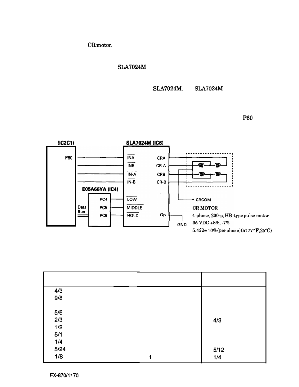
Carriage Motor Drive Circuit
The carriage motor drive circuit controls the CR motor. An open loop, constant-current drive
arrangement runs the
2-2 and 1-2 phases are used to excite the motor. A 2-2 phase step
is equivalent to a 1-2 phase step doubled. Table 6-6 describes the motor drive modes.
The CR motor drive circuit of the
(IC6) detects and regulates the amount of current
flowing in the carriage motor coil. The current flowing through the coil varies, depending on the
speed of the CR motor. The CPU sets the amount of current via the I/O port of the gate array.
Signals are sent to the ports (L, M, HOLD) on the
The
sets the coil current
depending on the CR motor speed.
The printer may stop printing to protect the CR motor from overheating if a continuous printing
of short columns (less than 10 columns) is repeated. The printer uses CPU ports
to P63
exclusively to control the CR motor.
CPU
P61
P62
P63
CR MOTOR
ASSEMBLY
Speed Mode
1
2
Figure 6-27. Carriage Motor Drive Circuit
Table 6-6. Carriage Motor Drive Modes
PPS
4468
2-2
3840
2-2
3357
2-2
2800
2-2
2240
2-2
1680
1-2
1400
l-2
840
l-2
700
l-2
420
-2
Excitation Phase
Characters Printed
Super draft
Super draft copy
Draft 10 cpi
high
duty
NLQ
high duty
high
duty
6-27
Epson