Sealey TA203 User Manual
Page 4
4.13.
Temperature Measurements
4.13.1. Insert the type K thermocouple plug into the negative “COM” jack and the positive jack ensuring the + symbol on the plug is inserted into the positive +
jack and the negative symbol on the plug is inserted into the negative “COM” jack.
4.13.2. Turn the rotary switch to the select °C or °F.
4.13.3. Read the temperature on the display.
4.14.
Pulse Width Measurements
4.14.1. Insert the black test lead into the negative “COM” jack and the red test lead into the positive “V” jack.
4.14.2. Turn the rotary switch to the ms-PULSE position.
4.14.3. Press the ± TRIG button for two seconds until the negative (-) trigger slope is displayed on the lower left of the display.
Note: The applied time for most fuel injectors is displayed on the negative slope.
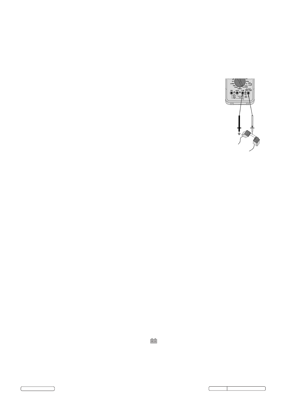
4.14.4.
Jumper wires between the fuel injector and the harness connector (fig.4.).
4.14.5. Connect negative test probe to a good ground at the fuel injector or the negative (-) vehicle battery post.
4.14.6. Connect the red test probe to the fuel injector solenoid driver input on the jumper cable.
4.14.7. Start the engine. A pulse width in milliseconds should be read.
Note: If the reading is to high or unstable, adjust the trigger level by pressing the ± TRIG button repeatedly.
4.15.
RPM (TACH) Measurements
4.15.1. Select the RPM range with the rotary switch.
4.15.2. Select the X10 RPM range with the rotary switch. Multiply the displayed reading times by 10 to get the actual RPM.
4.15.3. Press STROKE button (fig.1.12.) to select through RPM 4 for 4-stroke or RPM 2 for 2-stroke DIS.
Note: RPM4 for RPM of 4-stroke engines which have 1 ignition on every 4 engine strokes.
RPM2 for RPM of DIS (Distributerless Ignition System) & 2-Stroke engines which have 1 ignition on every 2
engine strokes.
4.15.4. Insert the inductive pickup leads into the meter. Black lead into the negative “COM” jack and the red lead into the positive
RPM jack.
4.15.5. Connect the inductive pickup to a spark plug HT lead and press the ± TRIG button once. If no reading is received, unhook
the
clamp, turn it over and connect again.
Note: Connect the pickup as far away from the distributor and exhaust manifold as possible.
Position the pickup to within six inches of the spark plug or move it to another plug HT lead if no reading or an erratic reading
is
obtained.
The inductive pickup has an adjustable sensitivity switch that may also be used to correct an unstable reading.
4.16.
Dwell Angle Measurement
Dwell angle is the number of degrees through which the distributor cam rotates while the breaker points are closed.
4.16.1. Insert the black test lead into the negative “COM” jack and the red test lead into the positive “V” jack.
4.16.2. Turn the rotary switch to the dwell position.
4.16.3. Set number of cylinders with the CYL button (fig.1.11.).
4.16.4. Connect the black test lead to the Ground terminal (-) on the car battery and the red test lead to the contact breaker points or the negative (-) terminal
of the ignition coil.
4.16.5. When the engine is started the Dwell will be displayed.
Note:
To reduce the dwell angle reading the points gap must be increased, to increase the dwell angle the points gap must be reduced.
Refer to your owners handbook for detailed procedures for dwell settings and adjustments.
4.17.
Other functions
4.17.1. Your meter is also capable of testing the following automotive sensors.
Oxygen Sensors
Fuel Injectors
Temp Sensors
Position Sensors
absolute pressure (MAP) and Baro Sensors
Mass Air Flow (MAF) Sensors
4.17.2. For a detailed description and testing procedure for these sensors, please refer to the vehicles hand book.
4.18.
Windows® Application Program (fig.6.)
Software requirements: Windows® 2000, ME or XP.
Supplied with USB optically isolated cable and Windows® compatible software allowing the user to collect, display, plot and save data.
4.18.1. Insert the Drivers CD-ROM into the computer.
4.18.2. Connect the optical interface end of the lead to the TA203 device and fasten the screws.
4.18.3. Connect the USB end of the lead to a free USB port on the computer. Windows will find new hardware and the "Found New Hardware Wizard" will begin,
to install the drivers using the Wizard please follow the steps below:
·
When asked "Can Windows connect to Windows Update to search for software?" select "No…" click "Next".
·
On the following screen select "Install from a list or specific location", click "Next".
·
Select "Don't search…" click "Next".
·
Scroll down the "Common hardware types" and highlight "Ports (COM & LTP)", click "Next".
·
Click the "Have Disk" Button, on the pop-up click "Browse" and browse to the CD drive in which the drivers disk has been placed then double
click the "USB driver" folder. This will show 4 files. Click "Open" then "OK".
·
Under "Model" it should list "CP2101 USB Composite Device", click "Next".
·
The drivers for that device will be loaded onto the system. Click "Finish" when completed.
4.18.4. The computer will then find another device and the Wizard will begin again, follow the steps as above again to install the drivers for the second device.
This time it should find a different device model called "CP2101 USB to UART Bridge Controller".
4.18.5. After driver installation, a new COM port will be added to the "Ports (COM &LPT)" section in the Device Manager. Within this section you will find a
device called "CP2101 USB to UART Bridge Controller" and next to it in brackets will be the (COM#), remember this number for entry into the data
logging application.
4.18.6. To install the logging application browse to the CD-ROM and double click "9995USB_4.0.exe". Then follow these steps:
·
Click "Next" on the first screen of the setup Wizard, enter something in the "User" and "Company" fields, click "Next".
·
Leave the "Install 9995 to" location on "C:\Program Files\9995", click "Next".
·
On the next screen click "Next" and the same on the following screen.
·
The program will be installed, when done click "Finished".
4.18.7. To run the program go to "All programs" within the "Start" menu and find "9995" and select "9995.exe".
4.18.8. Click button "A" (Fig.6) to toggle between available COM ports until the COM# in window "B" (Fig.6) matches the number found in the device manager
in step 4.18.5.
4.19.
Replacing The Battery
WARNING! To avoid electric shock, disconnect the test leads from any source of voltage before removing the battery door.
4.19.1. When the battery becomes exhausted or drops below the operating voltage, will be appear in the right hand side of the display. Replace the battery.
4.19.2. Disconnect the leads from the meter.
4.19.3. Open the battery door by loosening the screw using a Phillip’s screwdriver (fig.5.).
4.19.4. Remove the old battery and insert the new one, observing the correct polarity.
4.19.5. Replace the battery cover and secure with the two screws.
WARNING! To avoid electric shock, DO NOT operate the meter until the battery cover is secured
in place.
fig.4.
Original Language Version
© Jack Sealey Limited
TA203.V2 Issue No: 3(L)- 17/06/14