Operation – Sealey TA203 User Manual
Page 3
WARNING! Ensure that you read, understand and apply the safety and operational instructions before connecting the meter. Only when you are sure that
you understand the procedures is it safe to proceed with testing.
WARNING! Risk of electrocution. High voltage circuits, both AC and DC are very dangerous and should be measured with great care.
Operating temperature range 0°C to 40°C.
Remember to turn on meter before use and to turn it off when measurement is completed.
Note: IF “OL” appears in the display during a measurement, the value exceeds the range you have selected. Change to a higher range.
Note: On some low AC and DC ranges, with the test leads not connected to a device, the reading may show a random fluctuating reading. This is
normal and is caused by the high input sensitivity. The reading will stabilise and give a proper measurement when connected to a circuit.
4.1.
Mode Button (fig.1.12)
4.1.1. Press the Mode button to toggle between the AC and DC in the voltage & current measurements.
4.2.
Range/#CYL Button (fig.1.10)
4.2.1. The range is automatically selected by the meter.
4.2.2. To manually select a range or DWELL (#CYL) range within a function, press the range button.
4.2.3. To exit the range mode and return to autoranging, press and hold the range button for two seconds.
Note: If the range is to high, the meter will be less accurate.
If the range is to low, the meter displays ‘OL’ (Over Limit).
4.3.
Data hold, Backlight button (fig.1.4.)
4.3.1. The data hold function allows the meter to freeze a measurement reading for later reference.
4.3.2. Press the data hold button once to freeze the reading in the display. The indicator “hold” will appear in the display.
4.3.3. Press the data hold button again to return to normal operation.
4.3.4. Press and hold the data button for two seconds to to switch on the display back light.
4.3.5. Press and hold the data button again for two seconds to turn off the back light.
4.4.
Relative Button (fig.1.3.)
4.4.1. The relative measurement feature allows you to make measurements relative to a stored reference value. A reference voltage, current etc can be stored
and measurements made in comparison to that value. The displayed value is the difference between the reference value and the measured value.
4.4.2
Perform any measurement as described in the operating instructions.
4.4.3. Press the relative button to store the reading in the display and the “REL” indicator will appear in the display.
4.4.4. The display will now indicate the difference between the stored value and the measured value.
4.4.5. Press the relative button to return to normal operation.
4.5.
± Trig Button (fig.1.11.)
4.5.1. To toggle between the Negative (-) and Positive (+) Trigger slope when the meter is in the ms-pulse, %duty cycle mode.
4.5.2. Press and hold for two seconds to toggle between Negative (-) and Positive (+) Trigger slope.
4.5.3. Press the button repeatedly to adjust the trigger level if the meter reading is to high or unstable.
Note: The Trigger level has five steps and is different for each function combination.
4.6.
MAX/MIN/RS232 (fig.1.2.)
4.6.1. Press the MAX/MIN to enter MAX, MIN mode.
Note: MAX/MIN function is only available in the manual range.
4.6.2. Select the proper test range before activating the MIN/MAX button to ensure that the MIN/MAX reading will not exceed the testing range.
4.6.3. Press once to select MAX, press again to select MIN.
4.6.4. Press again to release MAX/MIN recording function.
4.6.5. Press and hold down for two seconds to activate the RS232 PC interface mode.
4.7.
AC or DC Voltage Measurements
4.7.1.
Insert the black test lead into the negative “COM” jack and the red test lead into the positive “V” jack.
4.7.2. Turn the rotary switch to the ‘V’ position.
4.7.3. Press the “MODE” button to select ac or dc voltage.
4.7.4. Touch the test probes to the circuit under test and read the voltage display.
4.8.
AC or DC Current Measurements
WARNING! Do Not make current measurements between 1A and 20A for longer than 30 seconds in every 15 minutes. Exceeding 30 seconds
may cause damage to the meter and test leads.
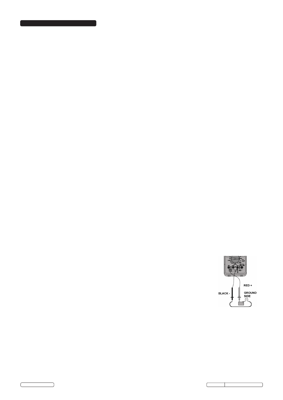
4.8.1. Insert the black test lead into the into the negative “COM” jack and the red test lead into the:
a) Positive uA/mA jack for currents to 400mA (fig.1.8.)
b) Positive 20A jack for currents to 20A (fig.1.9.)
Note: If you are unsure of the current draw select the 20A jack.
4.8.2. Turn the rotary switch to the uA, mA or A position.
4.8.3. Press the mode button to select AC or DC current.
4.8.4. Touch the test probes in series (fig.3.) with the circuit under test and read the current on the display.
4.9.
Resistance, Diode, Continuity Measurements
WARNING! To avoid electric shock, disconnect power to unit under test and discharge all capacitors before taking
any resistance or capacitance measurements.
4.9.1. Insert the black test lead into the negative “COM” jack and the red test lead into the positive “V” jack.
4.9.2. Turn the rotary switch to the Ω position.
4.9.3. Press the Mode button (fig. 1.12.) to select Ω, Diode or continuity.
4.9.4. Connect the test probes to the two ends of the Resistance, Diode, Continuity circuit to be measured.
4.9.5. Read the measured value from the display.
4.9.6. When measuring the forward voltage across a good Diode, it will indicate 0.4V or 0.7V will be indicated and the reverse
voltage will indicate “OL” (same as on open condition). For a short circuit diode, a value of 0mV will be displayed.
4.9.7. In continuity mode a complete circuit will beep continuously, if open circuit, there will be no beep.
4.9.8. In resistance measurements, if greater accuracy is required press the Range button.
4.10. Capacitance
WARNING! When checking in-circuit capacitance, be sure to disconnect the power supply from the circuit and that
the capacitors are fully discharged. The range control mode in capacitance measurement is auto-ranging.
4.10.1. Insert the black test lead into the negative “COM” jack and the red test lead into the positive “V” jack.
4.10.2. Turn the rotary switch to the CAP position.
4.10.3. Touch the test probes to the ends of the capacitor and read the capacitor value on the display.
4.11. Frequency(Hz)
4.11.1. Insert the black test lead into the negative “COM” jack and the red test lead into the positive “V” jack.
4.11.2. Turn the rotary switch to the “Hz” position.
4.11.3. Connect the negative “COM” test probe to ground.
4.11.4. Connect the positive “V” test lead to the “signal out” wire of the sensor to be tested.
4.12.
Duty Cycle (%)
4.12.1 Select the %DUTY range with the rotary switch.
4.12.2. Insert the black test lead into the negative “COM” jack and the red test lead into the positive “V” jack.
4.12.3. Connect the negative test probe to ground.
4.12.4. Connect the positive test probe to the signal wire circuit.
Fig.3.
4. OPERATION
Original Language Version
© Jack Sealey Limited
TA203.V2 Issue No: 3(L)- 17/06/14