Fig.9, Maintenance 6. technical specifications – Sealey TA200 User Manual
Page 5
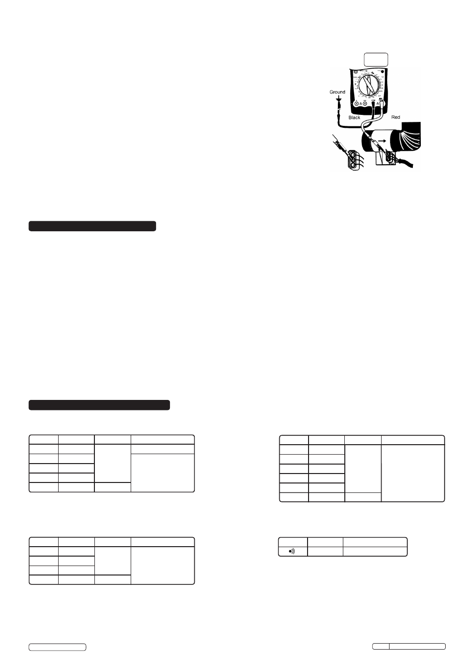
4.8. Mass Air Flow (MAF) Sensor (fig 9)
4.8.1. A mass air flow sensor converts air flow readings into one of the following, depending on the
sensor:
a) a DC voltage
b) a low frequency signal
c) a high frequency signal
The TA200 is suitable for testing those sensors with a DC voltage or low frequency signal
output.
4.8.2. Connect the DC voltage type MAF sensor in the DC voltage testing fashion (see section 4.1)
and set the rotary switch on the meter to 20V DC. For a low frequency signal type MAF
sensor, connect the meter in the RMPx10 testing fashion (see section 4.7) and choose the
appropriate setting for number of cylinders.
4.8.3. Connect the black test lead probe to the ground terminal of the sensor and connect the red
one as illustrated in fig 9.
4.8.4. Switch on the meter and the vehicles ignition but
DO NOT start the engine.
4.8.5.
DC Voltage type sensor: The displayed value should usually be less than or equal to 1V
(consult the vehicle manufacturer’s specifications).
4.8.6.
Frequency type sensor: Refer to the vehicle manufacturer’s specifications to compare
against your readings.
4.9. Other functions
4.9.1. The TA200 can also be used to test the following automotive components:
Oxygen sensors, fuel injectors, temperature sensors, position sensors, MAP and baro
sensors.
4.9.2. Please refer to the vehicle manufacturer’s manual for specific test procedures.
WARNING! DO NOT attempt to repair or service your meter unless you are qualified to do so and have the relevant calibration,
performance test and service information.
5.1. General maintenance:
5.1.1. Periodically wipe the case with a damp cloth and mild detergent.
DO NOT use abrasives or solvents.
5.1.2. Clean the terminals with a cotton bud and mild detergent to prevent the build up of dirt/moisture in the terminals which may affect readings.
5.1.3. Turn the meter off when not in use and remove the battery if the meter is not to be used for some time.
5.2. To replace the fuses:
5.2.1. Turn the meter off and disconnect any leads/equipment from the terminals.
5.2.2. Remove the protective rubber jacket from the meter.
5.2.3. Remove the 3 larger screws from the rear of the case and open the meter.
5.2.4. Remove the fuse in question and replace with a fuse of identical type and specification:
Fuse 1: CE 315mA, 250V, fast type, 5x20mm
Fuse 2: CE 10A, 250V, fast type, 5x20mm
5.2.5. Close the meter case and replace the three screws and rubber jacket.
5.3. To replace the battery:
5.3.1. Turn the meter off and disconnect and leads/equipment from the terminals.
5.3.2. Remove the small screw holding the battery compartment lid, then remove the lid and the old battery.
5.3.3. Place a new 9V (PP3) battery into the meter taking care to observe the correct polarity.
5.3.4. Replace the battery compartment lid and the holding screw.
Range Resolution Accuracy Overload protection
200mV
0.1mV
2V
1mV
20V
10mV
200V
100mV
230V AC
±(0.5%+5)
1000V DC or
750V AC continuous
1000V
1V
±(0.8%+5)
DC Voltage
Range Resolution Accuracy Overload protection
2V
1mV
20V
10mV
200V
100mV
±(0.8%+5)
1000V DC or
750V AC continuous
750V
1V
±(1.0%+4)
AC Voltage
Range Resolution Accuracy Overload protection
200Ω
0.1Ω
2kΩ
1Ω
20kΩ
10Ω
200kΩ
100Ω
600Vp
±(0.8%+5)
2MΩ
1kΩ
Resistance
2MΩ
10kΩ
±(1.5%+5)
Range Resolution Overload protection
1mV
600Vp
Continuity testing
Input impedance: 10MΩ
Input impedance: 10M
Frequency response: 40Hz ~ 400Hz
Original Language Version
5. MAINTENANCE
6. TECHNICAL SPECIFICATIONS
© Jack Sealey Limited
Fig.9
TA200 Issue No: 4(L) - 16/06/14