Fig.3 fig.4 fig.5, Operation – Sealey TA200 User Manual
Page 3
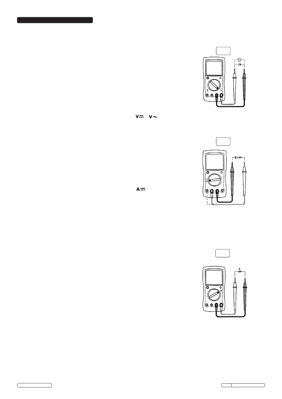
4.1. AC or DC voltage testing (fig 3)
WARNING! To reduce risk of electric shock, DO NOT attempt to measure voltages
higher than 1000V.
The measurement ranges DC voltage are 200mV, 2V, 20V, 200V and 1000V.
The measurement ranges AC voltage are 2V, 20V, 200V and 750V.
Select the range appropriate to the expected reading.
If the voltage to be measured is unknown, use the maximum measurement position
(1000V DC, 750V AC) and reduce the range, step by step until a satisfactory reading is
obtained. Should the meter become overloaded, the LCD will display “1”. This indicates that
a higher range must be selected.
In each range, the meter has an input impedance of approx 10M
Ω.
This may give rise to
measurement errors when dealing with high impedance circuits.
If the circuit impedance is <= 10k
Ω,
the error is negligible (0.1% or less).
4.1.1. To measure DC or AC voltage, connect the meter as follows:
4.1.2. Insert the red test lead into the “V” terminal and the black test lead into the “COM” terminal.
4.1.3. Set the rotary switch to an appropriate measurement position in or
4.1.4. Connect the test leads across the source being measured. The measured value will be
displayed. When the measurement has been completed, disconnect the test leads from the
circuit being tested.
4.2. DC Current testing (fig 4)
WARNING! Never attempt an in-circuit current measurement where the open circuit
voltage between terminals and ground is greater than 250V. If the fuse burns out
during measurement, the meter may be damaged and the user may be injured. Always
use correct terminals, function and range for the measurement.
When the test leads are connected to the current terminals, DO NOT parallel them
across any circuit.
The measurement ranges for DC current are 200.0mA and 10.00A.
4.2.1. To measure DC current, use the following procedure:
4.2.2. Turn off/disconnect power to the circuit, discharge all high voltage capacitors.
4.2.3. Insert the red test lead into the mA or 10A terminal and the black test lead into the COM
terminal.
4.2.4. Set the rotary switch to an appropriate measurement position in . If the current to be
measured is unknown, use the maximum measurement position (10A) and the 10A terminal,
then reduce the range step by step until a satisfactory reading is obtained.
4.2.5. Break the current path to be tested, connect the red test lead to the positive side of the
break and the black test lead to the negative side of the break (i.e. connect the meter in
series).
4.2.6. Turn on/reconnect power to the circuit. The measured value is shown on the display.
When the measurement has been completed, disconnect the test leads from the circuit being
tested.
Note: Within the 10A range, the meter must not be used for a period of greater than 10 seconds
more than once in any 15mins.
4.3. Resistance testing (fig 5)
WARNING! To avoid damage to the meter and/or the devices being tested, disconnect
circuit power and discharge all the high-voltage capacitors before measuring
resistance.
Never attempt an in-circuit current measurement where the open circuit voltage
between terminals and ground is greater than 60V DC or 30V AC rms.
The measurement ranges for resistance are: 200
Ω
, 2k
Ω
, 20k
Ω
, 200k
Ω
, 2M
Ω
,
and 20M
Ω.
4.3.1. To measure resistance, connect the meter as follows:
4.3.2. Insert the red test lead into the
Ω
terminal and the black test lead into the COM terminal.
4.3.3. Set the rotary switch to an appropriate measurement position in
Ω.
4.3.4. Connect the test leads across the object being measured. The measured value will be
displayed.
Note: The test leads themselves can add 0.1-0.2
Ω
to the resistance measurement. To obtain
a precision reading in the low-resistance range (i.e. 200
Ω,
short-circuit the input terminals
using the test leads beforehand and record the measured resistance as x. Then measure the
resistance of the object under test and record this value as y.
y – x = Correct value of resistance
If the resistance reading ≥ 0.5
Ω
in the short circuit condition, the test leads may be loose or
damaged. If damaged, replace immediately with suitable leads from your authorised Sealey
dealer.
For high resistance (>1M
Ω)
several seconds may be required to obtain a stable reading and
it is recommended that you use short test leads.
Where there is no input, the meter displays “1”.
When resistance measurement has been completed, disconnect the test leads from the
circuit being tested.
Note: During any of the following testing procedures, the data hold function can be employed.
When the “
HOLD” button (see fig 1.2) is pressed, data hold is activated and the value
displayed at that instant on the LCD is held until the
HOLD button is pressed again, at which
point the LCD once more displays the current measured value.
Fig.3
Fig.4
Fig.5
Original Language Version
6. OPERATION
© Jack Sealey Limited
TA200 Issue No: 4(L) - 16/06/14