Chapter 4, Bios settings – Lanner FX-3210 User Manual
Page 36
31
Bios Settings
Chapter 4
Network Application Platforms
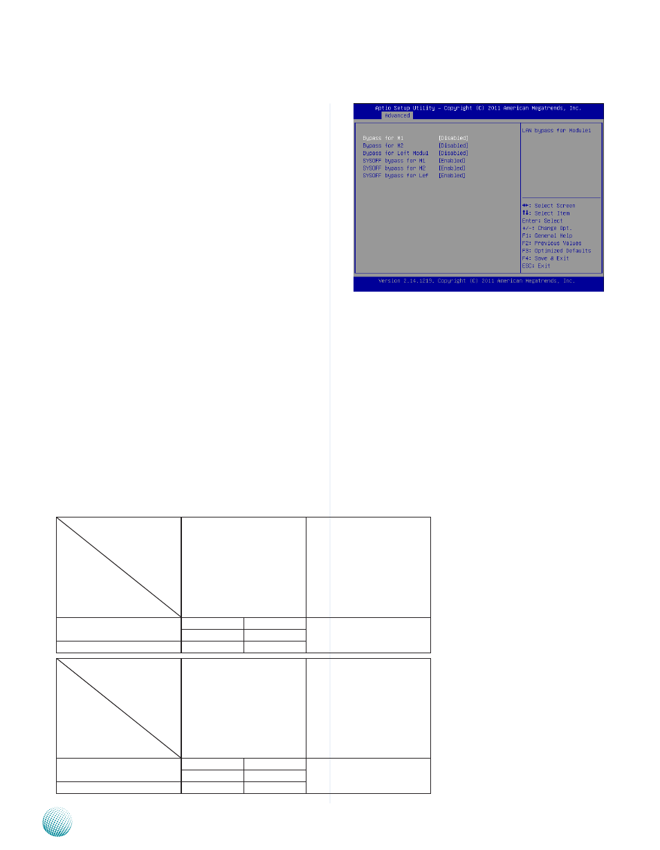
Lan Bypass Control
In this screen, you can configure the Lan Bypass
functionality. The system have 3 LAN modules: Left
module and two expansion models: M1 and M2 on the
right (when facing the front panel).
LAN Bypass for M1/M2/Left Modu1
You can activate or deactivate the Lan Bypass ports. For
the description of the physical ports that are capable of
the LAN Bypass function, refer to the Front Panel Feature in
M1 denotes Ethernet expansion module No.1 and M2
denotes Ethernet module No.2.
Left Modu1 denotes the module on the far left when
facing the front panel. Note that Left Modu1 also
supports Lanner Generation 3 Bypass. See appendix
D Programming Generation 2 and 3 LAN Bypass for
more information
SYSOFF bypass for M1/M2/Left Modu1
You can enable or disable the automatic activation of
hardware Lan Bypass function in the event of a power
failure. Hardware Bypass can automatically activate to
allow network traffic to continue.
The Lan bypass can be turned on or off in two system
states, i.e., power on and power off. The following are
the BIOS menu and illustration of the possibilities of LAN
bypass configuration in each state.
Bypass settings
System Status
LAN Bypass for Port1 and
Port 2
LAN Bypass 1&2 when
power off
Power on
Enabled
Disabled
Enabled
Bypass
Non-Bypass
Power off
Bypass
Bypass
Bypass settings
System Status
LAN Bypass for Port1 and
Port 2
LAN Bypass 1&2 when
power off
Power on
Enabled
Disabled
Disabled
Non-Bypass Non-Bypass
Power off
Non-Bypass Non-Bypass